4 Commissioning
Setting options via switches
EDK82ZAFVC010 DE/EN/FR 2.0
58
l
H1inbet−reihenfolge einhalten
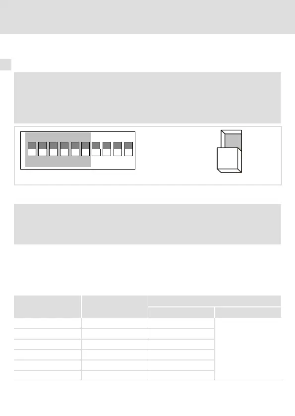
Node address setting
) Note!
The address must be set via software, when the switches S7 and S8 are in
ON−position.
In this case the switches S1 to S6 are ineffective.
ON
16274385 910
ON
OFF
Fig. 2 Node address setting
) Note!
If several controllers are connected to the network, the node addresses must
differ from each other.
The address (decimal number) is calculated by inserting the positions of switches S1 to S6
(’0’ = OFF and ’1’ = ON) into the following equation.
Address
dec
= S6 · 2
0
+ S5 · 2
1
+ S4 · 2
2
+ S3 · 2
3
+ S2 · 2
4
+ S1 · 2
5
The equation can also be used to calculate the valency of a switch. The sum of valencies
results in the node address to be set:
Switch Valency
Example
Switch position Node address
S1 32 ON
32 + 16+ 8 = 56
S2 16 ON
S3 8 ON
S4 4 OFF
S5 2 OFF
S6 1 OFF