Technical data
Terminal description
Axis modules
4
l
57
EDS700ACBA EN 5.1
Resolver
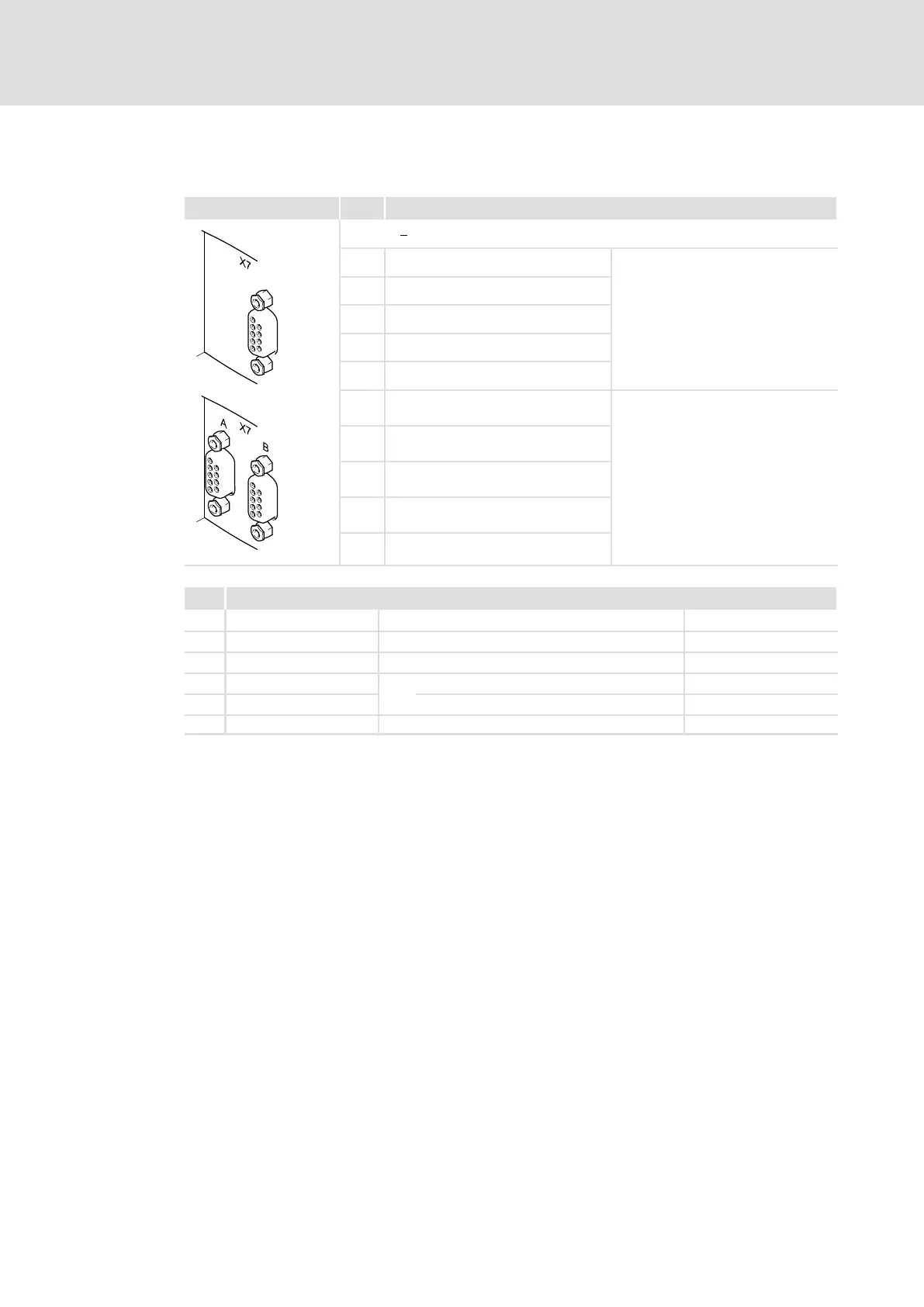
X7 Pin Description
E70ACM...R
1 +REF
On single axis devices, this
connection is located on the
right−hand side below the labelling
"X7".
2 −REF
3 n. c.
4 +COS
5 −COS
6 +SIN
On double axis devices, there are two
of these connections. For the
assignment to the axes, the
designations "A" / "B" are used.
7 −SIN
8 +KTY
9 −KTY
" Shield connection at Sub−D housing
i700AX007 a b
X7 Electrical data
General Cable length (system cable is recommended) Max. 50 m
3 n. c.
1, 2 +REF, −REF Input frequency max. 250 kHz
4, 5 +COS, −COS Excitation voltage 10 V
SS
6, 7 +SIN, −SIN Carrier frequency 4 kHz, constant value
8, 9 +KTY, −KTY Type KTY 83−110