Electrical installation
Installation according to EMC (installation of a CE−typical drive system)
Wiring outside of the control cabinet
6
l
99
EDS700ACBA EN 5.1
6.3.5 Wiring outside of the control cabinet
Notes for cable routing outside the control cabinet:
ƒ The longer the cables the greater the space between the cables must be.
ƒ If cables for different signal types are routed in parallel, the interferences can be
minimized by means of a metal barrier or separated cable ducts.
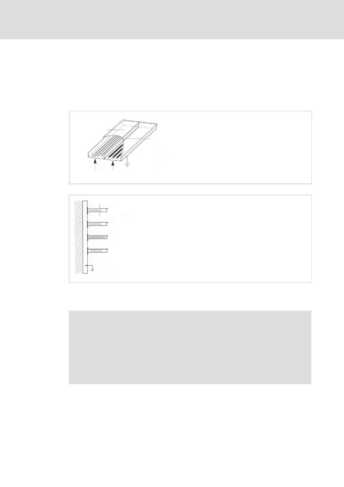
Cover
Barrier without
opening
Power cables
Signal cables
EMVallg001
Fig. 6−3 Cable routing in the cable duct with barrier
Cover
Communication cables
Cable duct
Measuring cables
Analog cables
Control cables
Power cables
EMVallg002
Fig. 6−4 Cable routing in separated cable ducts
Wiring on the motor side
) Note!
The motor cable is highly susceptible to interference. Therefore you will
achieve an optimum wiring on the motor side if you
ƒ exclusively use shielded and low−capacitance motor cables.
ƒ do not integrate any further cable into the motor cable (e.g. for blowers
etc.).
ƒ shield the supply cable for temperature monitoring of the motor (PTC or
thermostat) and install it separately from the motor cable.