Preface and general information
System block introduction
Definition of the inputs/outputs
1
25
EDBCSXA064 EN 3.2
Example:
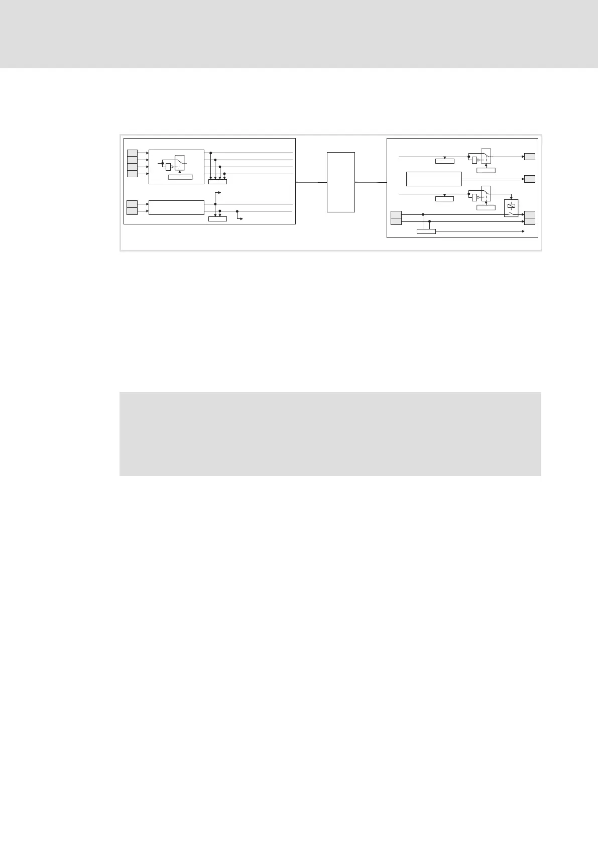
Use of the system blocks Inputs_Digital and Outputs_Digital
C0443
X6
Inputs_DIGITAL
DI3
SI1
SI2
DI1
DI4
DI2
safe standstill
1
0
C0114/1...4
1
X6
C0443
mP
mP + Imp
DIGIN_bIn1_b
DIGIN_bIn2_b
DIGIN_b_safe_standstill_b
DIGIN_bIn4_b
DIGIN_bIn3_b
DIGIN_bCInh_b
POE
Outputs_DIGITAL
X6
X6
1
0
C0118/1
DO1
SO
1
B-
B2
B+
1
0
C0118/2
1
B1
X25X6
safe torque off
C0444/1
C0444/2
C0602
MONIT-Rel1
DIGOUT_bOut1_b
DIGOUT_bRelais_b
ECSXA207
Fig. 1−2 Plan: connecting the system blocks "Inputs_Digital" and "Outputs_Digital"
If you want to use digital input 1 and digital output 1, carry out the following steps:
1. Explicitly integrate the system blocks Inputs_DIGITAL and Outputs_DIGITAL into the
control configuration of the DDS. ( 26)
2. For access to digital input 1:
– Assign the system variable DIGIN_bIn1_b to a POU variable.
3. For access to digital output 1:
– Assign the system variable DIGOUT_bOut1_b to a POU variable.
Note!
According to the IEC 61131−3 standard the system variables DIGIN_bIn1_b and
DIGOUT_bOut1_b may generally only be used once.
The use of one system variable in several POUs must be carried out via a copy
(as global variable).

 Loading...


