System modules
ANALOG1_IO (node number 11)
Inputs_ANALOG1 (analog input)
13
275
EDBCSXA064 EN 3.2
13.5 ANALOG1_IO (node number 11)
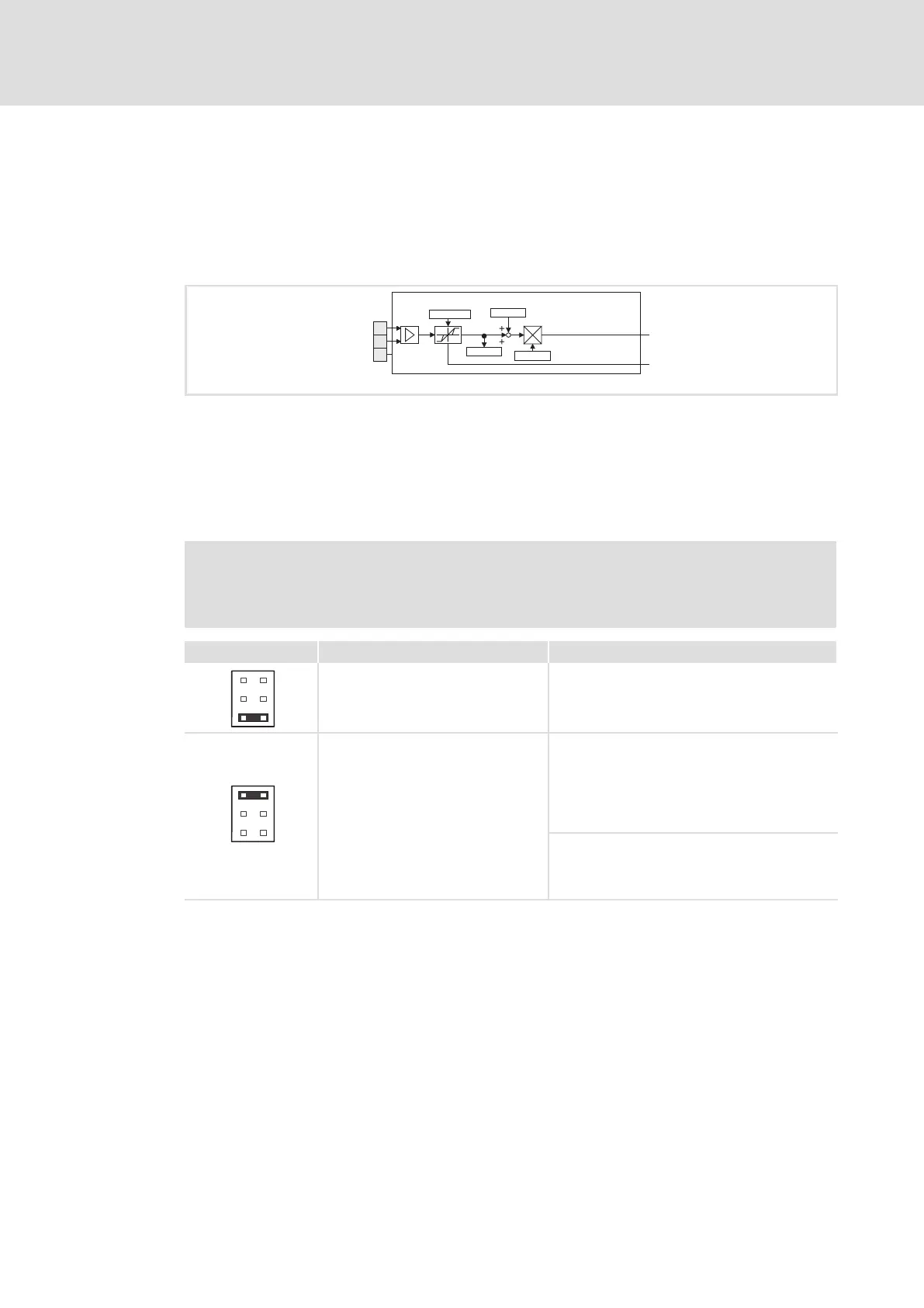
13.5.1 Inputs_ANALOG1 (analog input)
This SB represents the interface for analog differential signals via terminal X6/AI+, AI− as
a setpoint input or an actual value input.
AI-
AI+
AG
X6
C0034
C0026/1
C0400
C0027/1
AIN1_bError_b
AIN1_nIn_a
Inputs_ANALOG1
ECSXA221
Fig. 13−9 System block "Inputs_ANALOG1"
Analog input configuration
ƒ Use C0034 to set whether the input is to be used for a master voltage (±10 V) or a
master current (+4 ... 20 mA or ±20 mA).
ƒ Set jumper bar X3 according to the setting in C0034:
Stop!
Do not plug the jumper on the pins 3−4! The axis module cannot be initialised
like this.
Jumper bar X3 Setting Measuring range
6
4
2
5
3
1
5−6 open
Jumper on 1−2: Parking position
C0034 = 0 (master voltage)
l Level: −10 ... +10 V
l Resolution: 5 mV (11 bits + sign)
l Scaling: ±10 V º ±16384 º ±100 %
6
4
2
5
3
1
5−6 closed
C0034 = 1 (master current)
l Level: +4 ... +20 mA
l Resolution: 20 mA (10 bits without sign)
l Scaling:
+4 mA º 0 º 0 %
+20 mA º 16384 º 100 %
C0034 = 2 (master current)
l Level: −20 ... +20 mA
l Resolution: 20 mA (10 bits + sign)
l Scaling: ±20 mA º ±16384 º ±100 %
Use as master current input
ƒ Master current < 2 mA:
– Variable AIN1_bError_b = TRUE
– An error handling can be set via C0598.
ƒ Master current >= 2 mA:
– Variable AIN1_bError_b = FALSE

 Loading...


