Electrical installation
Control terminals
5
75
EDBCSXA064 EN 3.2
Shield connection of control cables and signal cables
The plate on the front of the device serves as the mounting place (two threaded holes M4)
for the shield connection of the signal cables. The screws used may extend into the inside
of the device by up to 10 mm. For optimum contact of the shield connection, use the wire
clamps from the ECSZS000X0B shield mounting kit.
L1 L2
L3
PE
X21
+UG
+UG
+UG
-UG
-UG-UG
PE
PEPE
X22
X23
+UG
BR1
BR0
T1
T2
X6
DI1
DI2
DO1
D24
+24V
GND
DO1
DI1
X6
DI2
DI3
DI4
AI+
AI-
AG
+24V
GND
S24
SO
SI1
SI2
B+
B-
+
-
=
24 VDC
+24 VDC
GND
U
F 1,6 A
3
4
+
-
=
"
"
"
"
"
"
"
0
2
1
ECSxE...
ECSxS/P/M/A...
ECSXA013
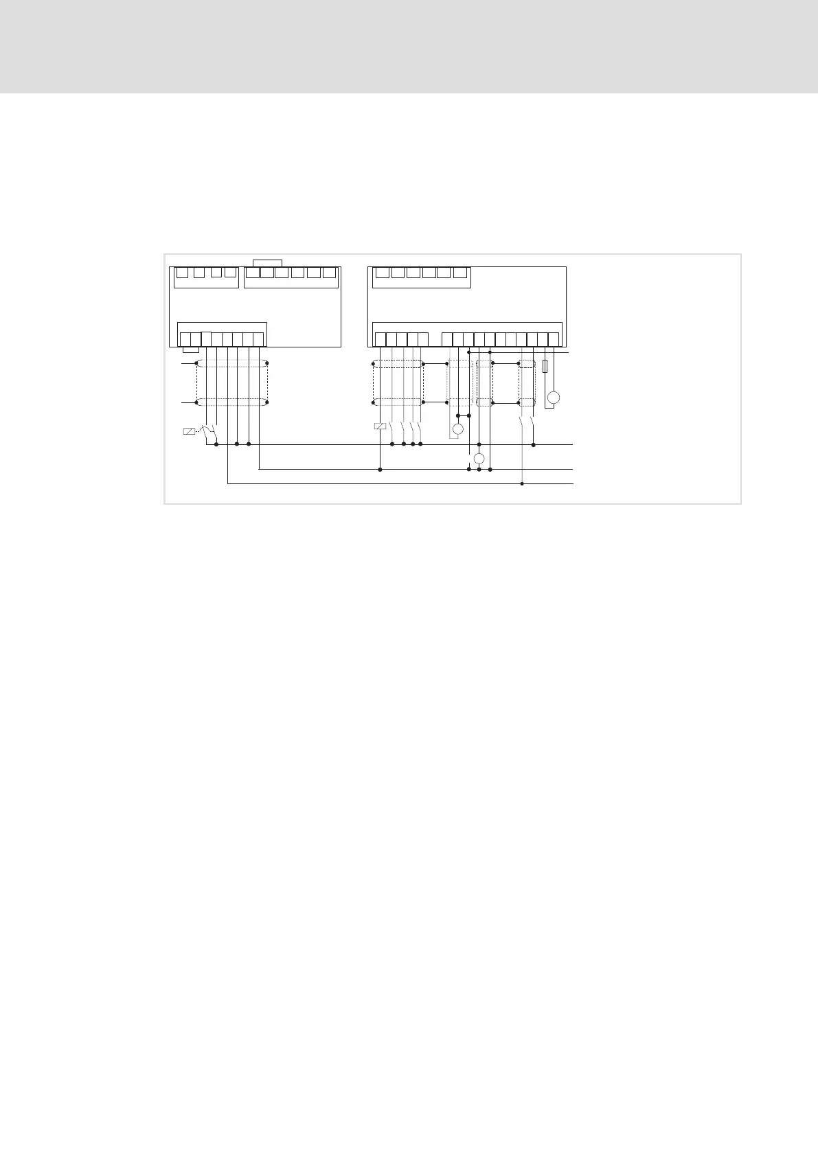
Fig. 5−8 Interconnection: Control signals with internal brake resistor
HF−shield termination by large surface connection to functional earth (see mounting
instructions for shield mounting ECSZS000X0B)
/ Contactor relay
Voltage supply of motor holding brake 23 ... 30 V DC, max. 1.5 A
Safe torque off (formerly: "Safe standstill")
Controller enable/inhibit

 Loading...


