Installation
4-29
L MA9300PLC EN 1.4
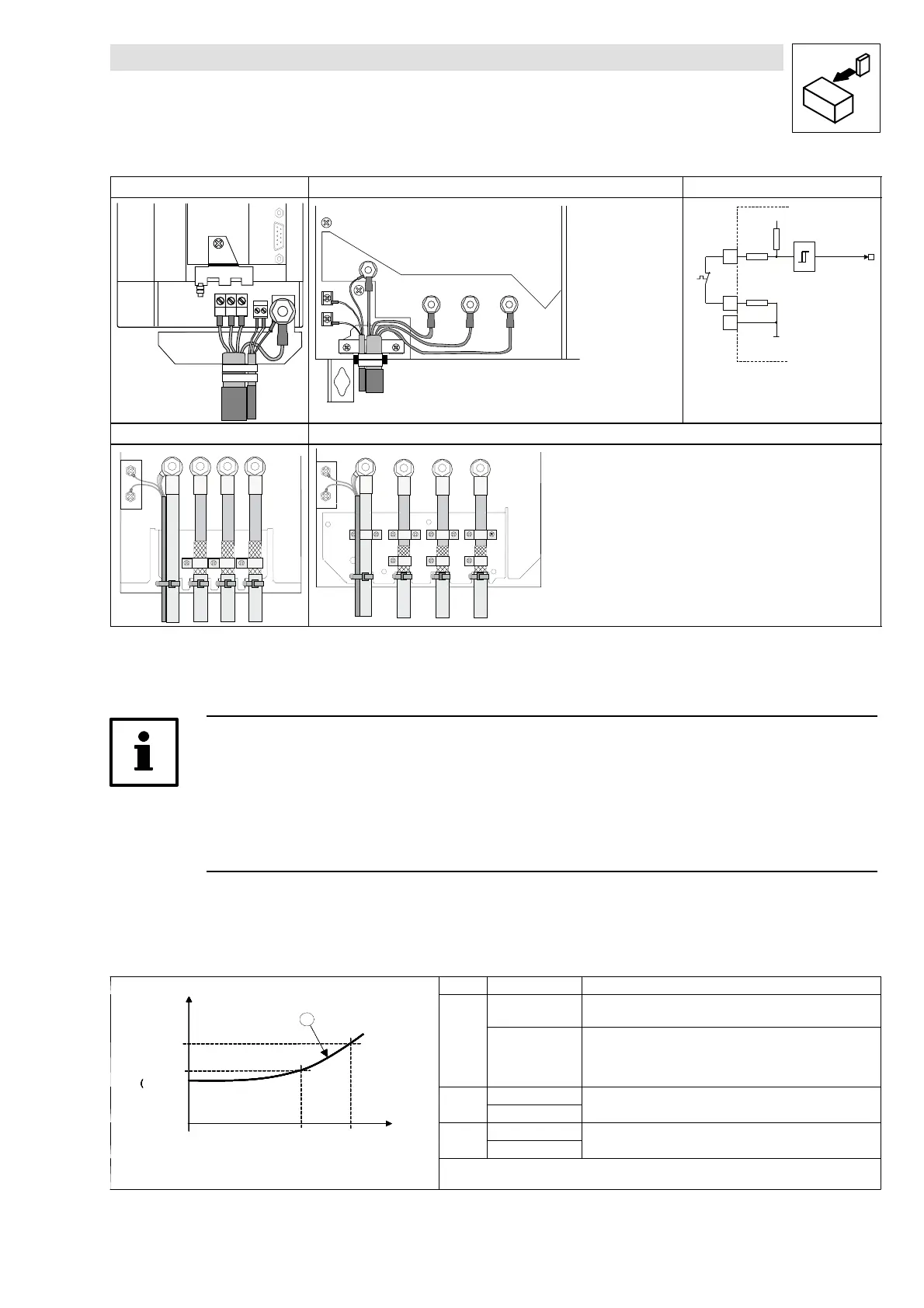
Types 9321 to 9326 Types 9327 and 9330 Internal connection
UVW
PE
U
V
W
X10
T1 T2
1
5
PE
T1
T2
UVW
MONIT-OH8
T1
T2
7
X6
24 V
93xx
K350052
ϑ
3,3k
7,4k
2,7k
Types 9330 and 9331 Type 9332
T1
T2
PE
UVW
T1
T2
PE
U
VW
Fig. 4-14 Connection of a thermal sensor to the terminals T1 and T2 and internal connection
Tip!
• In the prefabricated Lenze system cables for Lenze servo motors the cable for the
temperature feedback is already included. The cables are designed for wiring according to
EMC.
• If you use your own cables:
– Always lay cables separately from motor cables.
4.2.9.1 User-specific characteristic for a PTC thermistor
T [ ° C ]
R [ O h m ]
R 2
( C 1 1 9 2 / 2 )
T 1
( C 1 1 9 1 / 1 )
R 1
C 1 1 9 2 / 1 )
T 2
( C 1 1 9 1 / 2 )
a
Code Subcode Description
T [ ° C ]
R [ O h m ]
R 2
( C 1 1 9 2 / 2 )
T 1
( C 1 1 9 1 / 1 )
R 1
C 1 1 9 2 / 1 )
T 2
( C 1 1 9 1 / 2 )
a
C1190
0
(operating mode 1)
Evaluation of the Lenze standard motor temperature sensor
T [ ° C ]
R [ O h m ]
R 2
( C 1 1 9 2 / 2 )
T 1
( C 1 1 9 1 / 1 )
R 1
C 1 1 9 2 / 1 )
T 2
( C 1 1 9 1 / 2 )
a
1
(operating mode 2)
Evaluation of a user-specific thermal sensor. The operating
point is in the almost linear area (a) of the sensor
characteristic. The operating point is provided by two
interpolation points. Interpolation between these two points.
T [ ° C ]
R [ O h m ]
R 2
( C 1 1 9 2 / 2 )
T 1
( C 1 1 9 1 / 1 )
R 1
C 1 1 9 2 / 1 )
T 2
( C 1 1 9 1 / 2 )
a
C1191
1 (100 °C)
Definition of the temperature interpolation points which are
T [ ° C ]
R [ O h m ]
R 2
( C 1 1 9 2 / 2 )
T 1
( C 1 1 9 1 / 1 )
R 1
C 1 1 9 2 / 1 )
T 2
( C 1 1 9 1 / 2 )
a
2 (150 °C)
u
assigned to the resistances of the sensor.
T [ ° C ]
R [ O h m ]
R 2
( C 1 1 9 2 / 2 )
T 1
( C 1 1 9 1 / 1 )
R 1
C 1 1 9 2 / 1 )
T 2
( C 1 1 9 1 / 2 )
a
C1192
1 (1670 Ω
T [ ° C ]
R [ O h m ]
R 2
( C 1 1 9 2 / 2 )
T 1
( C 1 1 9 1 / 1 )
R 1
C 1 1 9 2 / 1 )
T 2
( C 1 1 9 1 / 2 )
a
2 (2225 Ω
e
n
n
esens
es
s
ances
Example of a sensor characteristic for continuous temperature
detection

 Loading...


