Installation
4-20
L
MA9300PLC EN 1.4
4.2.8 Control connections
4.2.8.1 Control cables
• Connect control cables to the screw terminals:
Max. permissible cable cross-section Screw-tightening torques
1.5 mm
2
0.5 ... 0.6 Nm (4.4 ... 5.3 lb-in)
• We recommend a one-sided shielding of all cables for analog signals, to avoid signal
distortion.
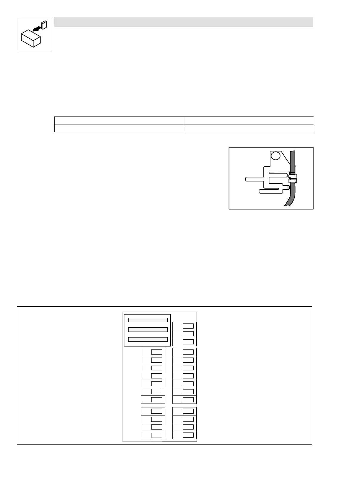
• Conntect the control cable shields to the shield plate and screw the shield plate to the front
metal surface (screw lenth max. 12 mm).
4.2.8.2 Assignment of control terminals
Protection against inverse polarity
• This protection prevents from wrong connection of internal control inputs. It is, however,
possible to overcome the protection against polarity reversal by applying great force. If so,
the controller cannot be enabled.
Overview
K35.0115
12
7
6 2
34
7
6 3
A 4S T
5 9
S T
A 3
A 2 A 1
E 3
E 53 9 E 4 E 2 E 1
2 8
G N D
L O
H I
X 5
X 6
X 4
Fig. 4-11 Layout of the control connections on the front of the controller

 Loading...


