Installation
4-21
L MA9300PLC EN 1.4
Terminal Use Level Data
Analog
inputs
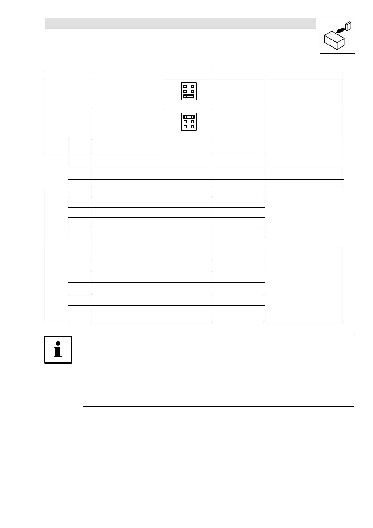
1, 2 Differential master-voltage input
6
4
2
5
3
1
-10Vto+10V Resolution:
5 mV (11 bit + sign)
Jumper X3
Differential master-current input
6
4
2
5
3
1
-20 mA to +20 mA Resolution:
20
µA (10 bit + sign)
Jumper X3
3, 4 Differential master-voltage input Jumper X3 has no ef-
fect
-10Vto+10V Resolution:
5 mV (11 bit + sign)
Analog
outputs
62 Monitor 1
(freely assignable)
-10Vto+10V;
max. 2 mA
Resolution:
20 mV (9 bit + sign)
63 Monitor 2
(freely assignable)
-10Vto+10V;
max. 2 mA
Resolution:
20 mV (9 bit + sign)
7 Internal earth, GND - -
Digital
28 Controller enable (RFR) HIGH active
LOW: 0 ... +4 V
u
E1 freely assignable HIGH active
:+
... +
E2 freely assignable HIGH active
Input current at 24 V:
8 mA per input
E3 freely assignable HIGH active
u
E4 freely assignable HIGH active
u
Shortest reading cycle: 1 ms (depen-
E5 freely assignable HIGH active
ding
n the gene
ati
nsite
the p
-
cess map)
Digital
ut
uts
A1 freely assignable HIGH active
LOW: 0 ... +4 V
I
: +13 ... +30
u
u
A2 freely assignable HIGH active
...
A3 freely assignable HIGH active
u
u
u
max. 50 mA per output
A4 freely assignable HIGH active
e
e
na
es
s
ance a
eas
a
24 V)
39 Earth of digital inputs and outputs -
Updating of the outputs:
59 Supply input for the control module:
24 V external (I > 1A)
-
h
test updating c
cle: 1 ms
depen-
ding on the generation site of the pro-
cess map)
Tip!
• To change the jumper, remove plug-on module, if necessary.
• A detailed description how to invert digital input and output levels can be obtained from
chapter ”DIGITAL_IO” in the Drive PLC Developer Studio (DDS) Manual.
• Use the function block L_AIN or L_AOUT to adjust the analog input and output signals.
Detailed information can also be obtained from ’Standard library 9300 Servo PLC’ in the DDS
Manual.
 Loading...


