Installation
4-30
L
MA9300PLC EN 1.4
4.2.10 Feedback systems
Different feedback systems can be connected to the controller:
• Resolver feedback (factory setting)
• Encoder feedback
– Incremental encoder TTL
– Sin-cos encoder
– Sin/cos encoder with serial communication (single turn)
– Sin/cos encoder with serial communication (multi turn)
Resolver signal or encoder signal can be output for slaves at the digital frequency output X10.
• Connection as shown in the figures:
– Use twisted pair cables and screened pair cables.
– Connect the screen at both ends.
– Use the indicated cable cross-sections.
• The feedback system is activated under C0025.
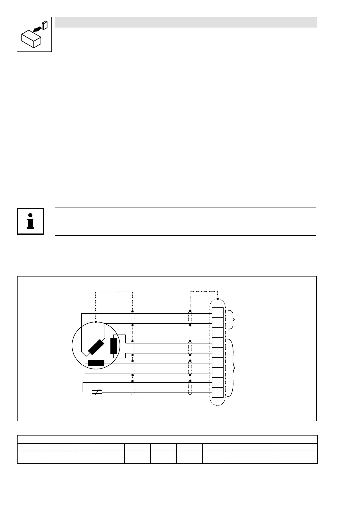
Resolver connection (X7)
• A resolver can be used as feedback system at this input. An adjustment is not necessary.
Tip!
Use the prefabricated Lenze system cable for the resolver connection.
Features:
• 2-pole resolver (V = 10 V, f = 4 kHz)
• Resolver and resolver cable are monitored for open circuit
(error message: Sd2, “ResolverFault”)
+ R E F
- R E F
+ C O S
- C O S
+ S I N
- S I N
R e s o l v e r
1
2
3
4
5
6
7
8
9
+ P T C
- P T C
P T C
X 7
9 p o l e S u b - D f e m a l e c o n n e c t o r
C a b l e l e n g t h m a x . 5 0 m
0 . 1 4 2 6
0 . 5 2 0
m m
2
A W G
Æ
Fig. 4-15 Resolver connection
Assignment of the female connector (X7)
Pin 1 2 3 4 5 6 7 8 9
Signal +Ref -Ref GND +COS -COS +SIN -SIN +PTC
(
^ 4-28 )
-PTC
(
^ 4-28 )

 Loading...


