Installation
L
36
EDBEPM-H310 DE/EN/FR 2.0
3.2 Electrical installation
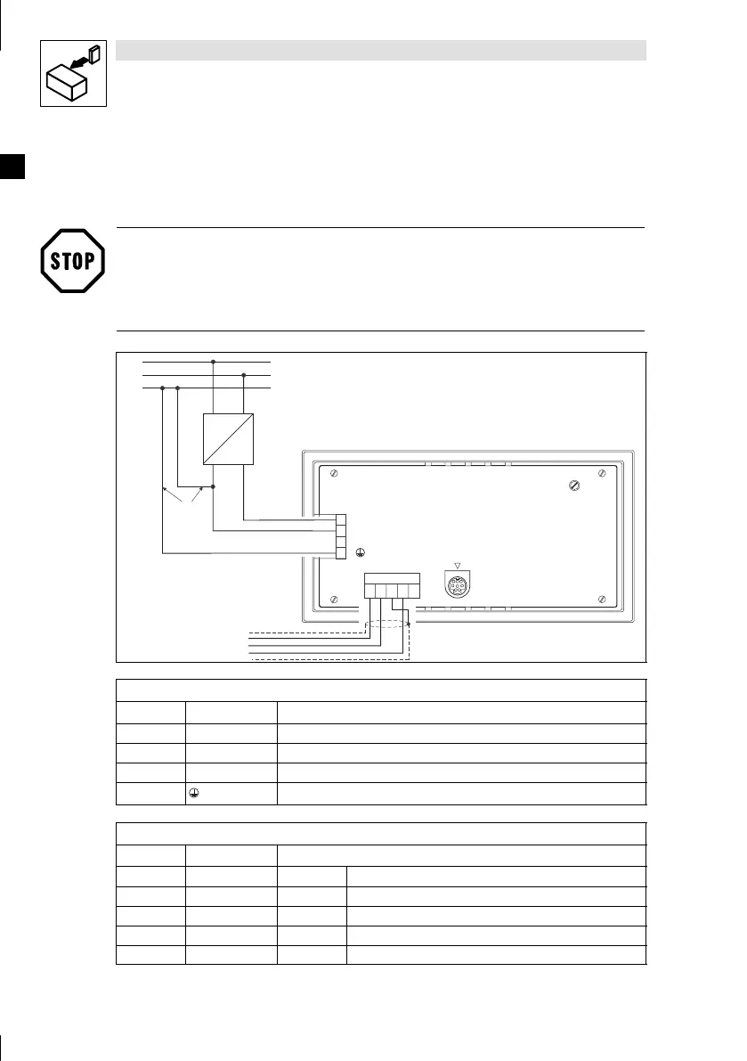
3.2.1 Assignment of the connection terminals
Stop!
Damage to the keypad and the connected PC can be avoided by
• wiring the keypad only when the voltage has been disconnected,
• connecting the PE conductor 0 asshowninthediagram.
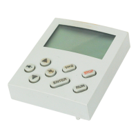
LCD ADJ
+24 VDC
INPUT: 18 - 32 V 5W
FUSE 315 mA
0 VDC
N.C.
ASP8
N.C.
CAN+
Shield
CAN-
V-
1
12345
2
3
4
PE
N
L1
CAN-GND
CAN-LO
CAN-HI
H310_003
0
~
–
+18...32VDC
DC voltage supply
Terminal Name Explanation
1 +24 VDC Voltage supply (18 V ... 32 VDC)
2 0VDC GND v oltage supply, reference potential
3 N.C. Not connected
4 PE potential
System bus (CAN)
Terminal Name Explanation
1 V- GND Reference potential
2 CAN- LO System bus LOW (data cable)
3 Shield - Connect the shield of the system bus cable
4 CAN+ HI System bus HIGH (data cable)
5 N.C. Not connected