Safety instrucons
Operang Instrucons i550 protec 5
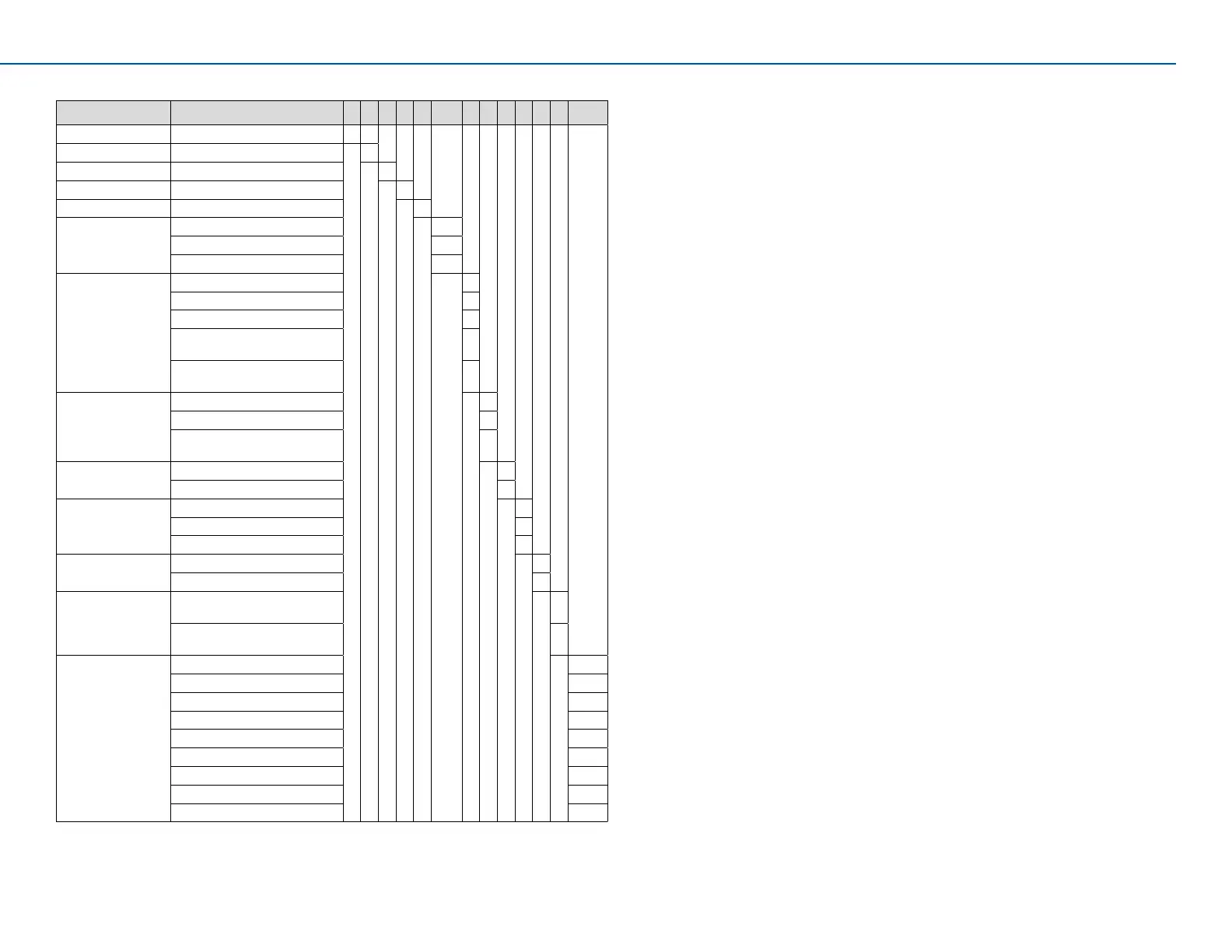
1.5 Idencaonoftheproducts
I 5 5 A P xxx x 1 x x x x xxxx
Product type Inverter I
Product family i500 5
Product i550 5
Product generaon Generaon 1 A
Mounng type Wall mounng P
Rated power
kW
(examples)
0.25 kW 125
0.55 kW 155
2.2 kW 222
Mains voltage and
connecon type
(examples)
1/N/PE AC 120 V A
1/N/PE AC 230/240 V B
3/PE AC 230/240 V C
1/N/PE AC 230/240 V
3/PE AC 230/240 V
D
3/PE AC 400 V
3/PE AC 480 V
F
Product extension None 0
Empty extension box 1
Service switch with
extension box
2
Integrated funconal
safety
Without safety funcon 0
Basic Safety STO A
Degree of protecon IP31, uncoated 3
IP54, uncoated 5
IP66, uncoated 7
Interference
suppression
Without 0
Integrated RFI lter 1
Operaon area Default parameter:
EU region (50-Hz networks)
0
Default parameter:
Region US (60-Hz networks)
1
Design types
(examples)
Standard I/O without network 000S
Standard I/O with CANopen 002S
Standard I/O with Modbus RTU 003S
Standard I/O with EtherCAT 00KS
Standard I/O with PROFINET 00LS
Standard I/O with Ethernet/IP 00MS
Standard I/O with Modbus TCP 00WS
Version with Keypad module K0XX
Version with WLAN module W0XX
2 Safetyinstrucons
2.1 Basic safety measures
Disregarding the following basic safety measures may lead to severe
personal injury and damage to property!
Observe all specicaons of the corresponding documentaon supplied.
This is the precondion for safe and trouble-free operaon and for
obtaining the product features as specied.
The product:
• must only be used as directed.
• must never be commissioned if they display signs of damage.
• must never be technically modied.
• must never be commissioned if they are not fully mounted.
• must never be operated without required covers.
• must only be disconnected from the installaon in de-energized
condion.
• Connect/disconnect all pluggable terminals only in de-energized
condion.
Deviceprotecon
• Carry out insulaon resistance tests between 24-V control potenal
terminals and PE. The maximum test voltage must not exceed
DC 110 V.
Process engineering
The procedural notes and circuit details given in this document are
suggesons and their transferability to the respecve applicaon has to
be checked. Lenze does not take responsibility for the suitability of the
process and circuit proposals.
 Loading...


