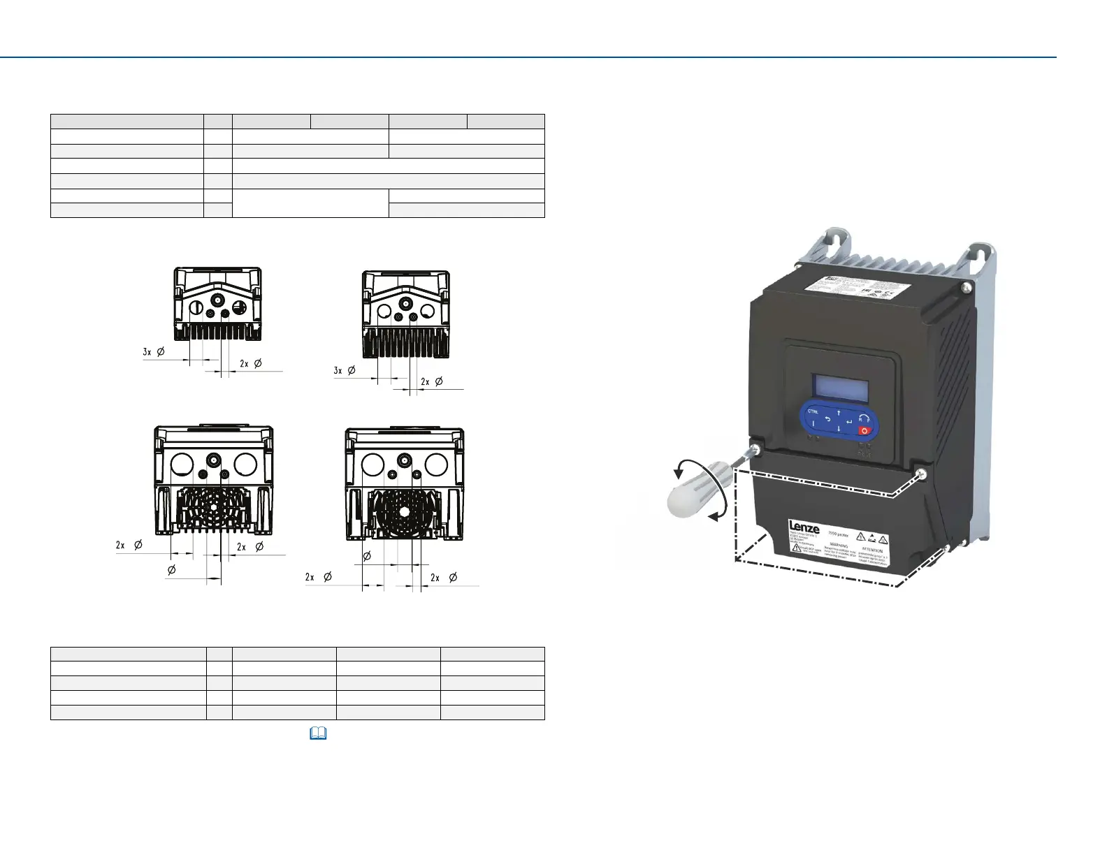
Open and close screw connecon of the cover
Operang Instrucons i550 protec 9
4.2 Cable entries with shield support
The cable glands are located on the underside of the device.
Rated power
kW 0.37 … 0.75 0.75 … 2.2 3 … 5.5 7.5 … 11
Ø Cable entry A mm 21.1 21.3
Number of holes 3 1
Ø Cable entry B mm 12.3
Number of holes 2
Ø Cable entry C mm 33.5
Number of holes 2
A
B
A
B
C
A
B
A
C
B
0.37 ... 0.75 kW
0.75 ... 2.2 kW
3 ... 5.5 kW
7.5 ... 11 kW
Suitable cable glands are e.g. Cable Glands Set Size 2 & 3 (EZAMBHXX022)
and Cable Glands Set Size 4 & 5 (EZAMBHXX023).
Operaon
Cable entry A Cable entry B Cable entry C
with cable gland M20 x 1.5 M12 x 1.5 M32 x 1.5
Max. external cable diameter mm 14 6.5 25
without cable gland
Max. external cable diameter mm 21 12 33
Also see “EMC-compliant installaon“. 10
5 Openandclosescrewconneconofthecover
► For wiring purposes, loosen the 4 screws in the cover using a crossp
screwdriver.
► Aer compleng the wiring, close the cover again using the 4 screws
to ensure that the degree of protecon is maintained.
PH2
1.2 Nm
10.6 lbin)
4x
 Loading...


