Electrical installation
Power supply modules
6
l
106
EDS700ACBA EN 5.1
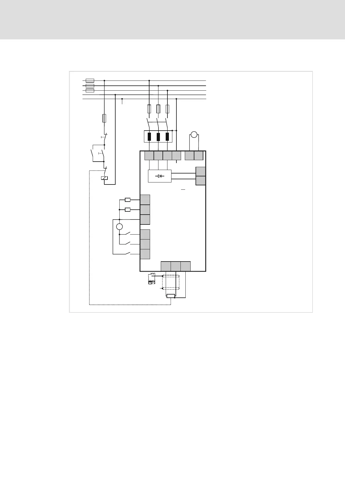
The basic circuit diagram provides a complete overview of the wiring of the devices.
X21
DC 24 V
(+19.2...
+28.8 V)
GE
24E
+
-
2
X20.2
X20.1
DC 24 V
(+19.2 ...
+28.8 V)
+
-
DO1
DO2
GD
DI1
DI2
DI3
X100
PE
L3
L2
L1
Rb1
PE
Rb2
X103
"
"
|
+
X102
-UG
+UG
X101
+
R
b
3 PE /AC 400/480 V
L1
L2
L3
N
PE
F1 … F3
K1
Z
F4
K1
K1
0
I
R
b
J
+
E70AC ...P
1
i700xxx
Fig. 10 Basic circuit diagram − power supply modules
E70ACP... i700 power supply module
F... Fuses
K Mains contactor with latch circuit
Z Filter
R
b
External brake resistor
24−V supply of digital inputs and outputs
24−V supply of control electronics

 Loading...


