Diagnostics
Display of operating data, diagnostics
Supply modules
9
l 126
EDS700ACBA EN 5.1
9 Diagnostics
9.1 Display of operating data, diagnostics
9.1.1 Supply modules
The passive power supply modules can only be diagnosed via the terminal outputs on the
device.
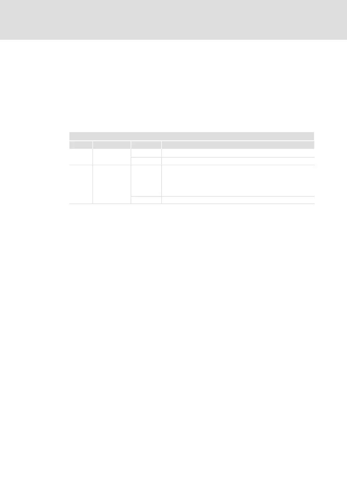
X20
Signal Name Status Description
DO1 Brake chopper
status
LOW Brake chopper not active or 24−V supply voltage off
HIGH Brake chopper active
DO2 Status message LOW l 24−V supply voltage is off
l Fault: Heatsink overtemperature
– no acknowledgement required
l Fault: Brake IGBT overcurrent/short circuit
– acknowledgement required:
HIGH 24−V supply voltage ok, module ready for operation
Acknowledgement of the status messages of the power supply modules by means of:
ƒ Applying of 24 V (HIGH) at input DI2.
ƒ Short−time switch−off of the 24−V supply voltage
– If the voltage supply cannot be switched off, terminal X21 can be unplugged
instead.
If the status cannot be acknowledged, the "overtemperature" or "overcurrent/short
circuit" fault persists.
9.1.2 Axis modules
To diagnose the axis modules, errors and warnings are mapped in "error codes" according
to the CiA 301/402 standard. Additionally, a history is available enabling a central logbook
to be set up in the control system. More detailed information can be found in the software
manual or in the online help.

 Loading...


