Electrical installation
Axis modules
6
l
108
EDS700ACBA EN 5.1
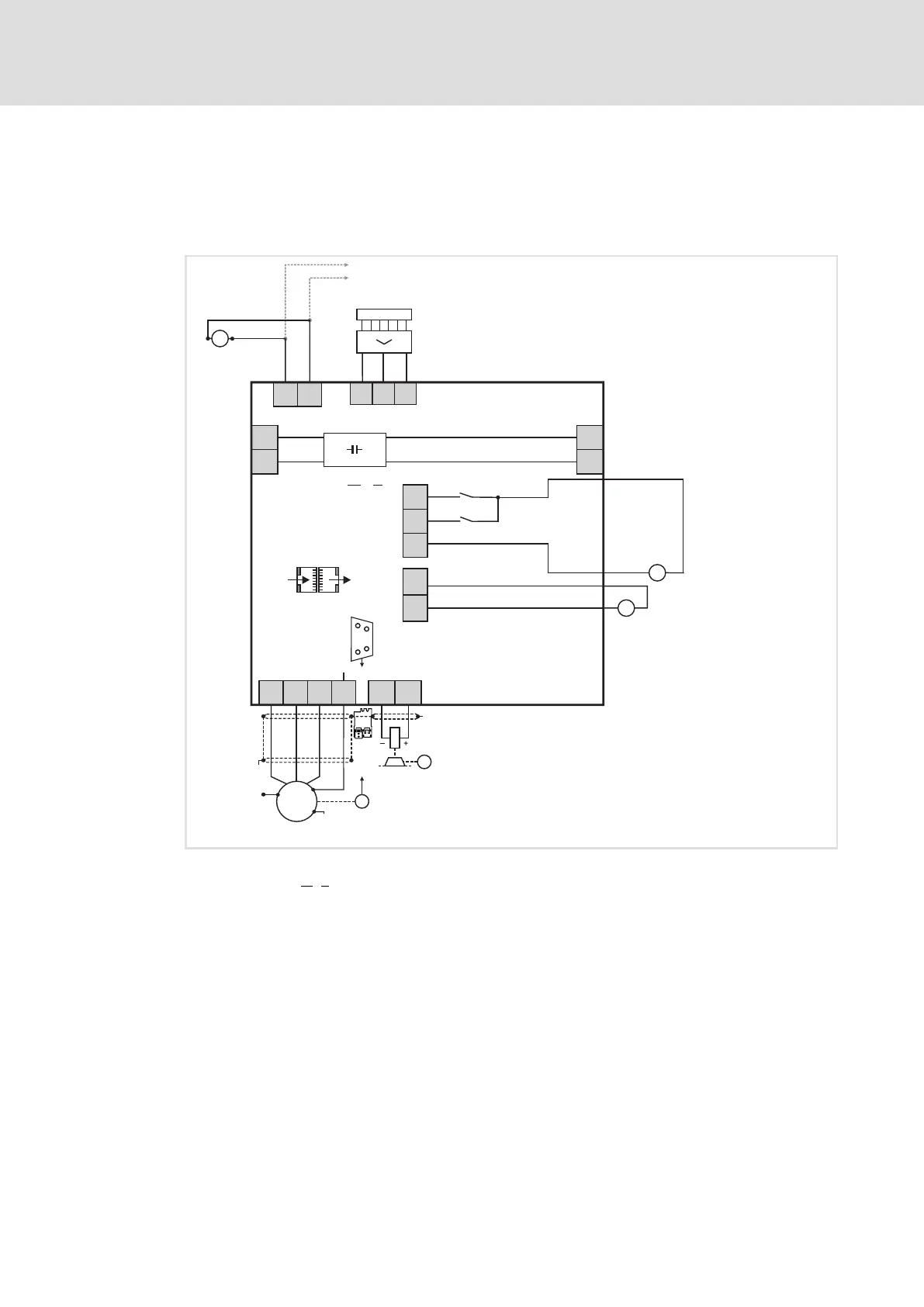
The basic circuit diagram provides a complete overview of the wiring of the devices.
Single axis module
SIBGSSIA
X1
DC 24 V
(+19.2...
+28.8 V)
DI1
DI2
GD
X2
+
-
... n
X3
X3
DC 24 V
(+19.2...+28.8 V)
GE
24E
-
+
DC 24 V
(+19.2...
+28.8 V)
+
-
2
X4
X5
...
R
R
DC 24 V
4
X105
24E
GE
+
-
"
M
BD1
BD2
X106
"
+
PE
WV
U
X108
"
"
M
3~
+
-UG -UG
+UG+UG
E70AC ...M1
3
i700S0012 A
Fig. 11 Basic circuit diagram − axis modules
E70ACM
...1 i700 "single inverter" single axis module − motor A
...n Other i700 axis modules
24−V supply of control electronics
24−V supply of digital inputs
24−V supply of motor holding brake(s)
R Servo control feedback (X7 = resolver or X8 = encoder)

 Loading...


