Electrical installation
Installation according to EMC (installation of a CE−typical drive system)
Shielding
6
l
94
EDS700ACBA EN 5.1
Realisation
i700EMV001 a i700EMV001 b
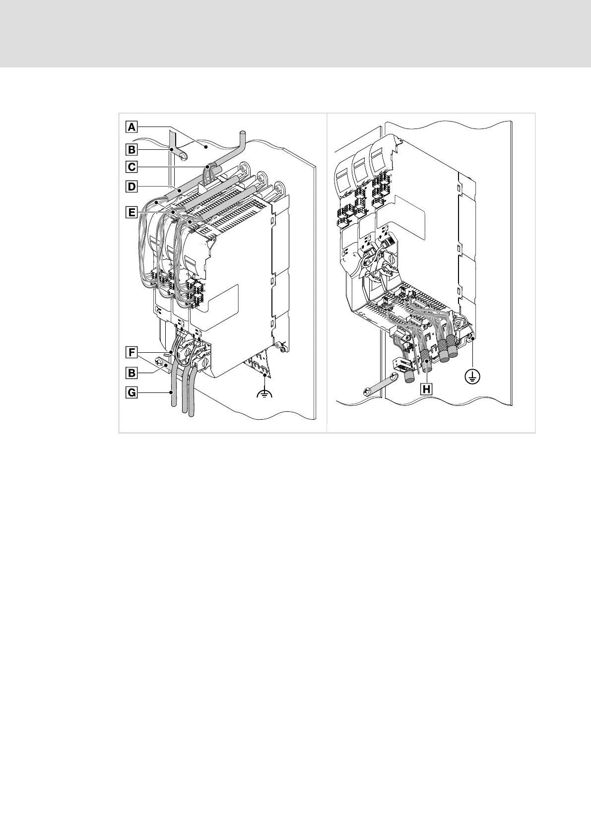
Fig. 6−1 Wiring in compliance with EMC standards
0
Mounting plate with electrically conductive surface
1
Earth connection of the control cabinet elements
2
Mains connection, unshielded cable
3
Bundling of cables in the conduit
4
Control cables and supply voltage, unshielded
5
System cables, EtherCAT® communication bus (scope of supply)
6
System cable for feedback, servo control
"
Integrated shield connection (functional earth) with shield clamp (scope of supply)
7
Shielded cables of the motor, motor holding brake and brake resistor connections
Motor cable, shielded, low−capacitance (see also technical data, page 30)
£ 2.5 mm
2
(AWG 14): Core/core £ 75 pF/m; core/shield £ 150 pF/m
³ 4.0 mm
2
(AWG 12): Core/core £ 150 pF/m; core/shield £ 300 pF/m
+
Integrated PE conductor connection

 Loading...


