Installation
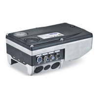
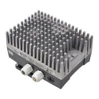
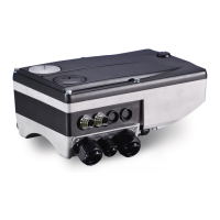
Connections of MOBILE DCU S
Addressing CAN bus nodes
5
Ò
65
EDSMDAG EN 2.0
Setting the address offset
Each MOBILE device has one address for the Public CAN and up to three addresses for the
Private CAN. An address consists of the basic address and the address offset (address =
basic address + address offset).
ƒ Lenze setting of the address offset: 13 (ID pins are not wired)
ƒ Lenze setting of the basic address for Public−CAN: 247
ƒ Lenze setting of the basic addresses Private−CAN:
– AppC: 45
– MC (channel 1): 14
– MC (channel 2): 77
Each device has one address for the Public CAN and three addresses for the Private CAN. An
address results from the addition of the basic address and the address offset (0...3).
The address offset is defined by wiring ID−Pin1...ID−Pin3 to X1. Thanks to the
combinations, 4 different address offsets are possible which means that up to 4 MOBILE
devices can be operated at a CAN bus.
Boot-
Loader
Startup
13
0
1
3
ID-Pin1 ID-Pin2 ID-Pin3Offset
EMDAG031
Fig. 5−4 Wiring at X1
ID−PIN1 X1/18
ID−PIN2 X1/19
ID−PIN3 X1/20
Offset 13 Lenze setting
Boot Loader Startup Device remains in the Boot Loader, firmware is not started.
The length of the wire jumpers may be maximally 50 mm. If the ID pins are double assigned, the
contact must be double crimped.

 Loading...


