Lenze 13466187 EDBTL03 v8 EN, DE, FR, IT, ES 9
Installation
Type
Installation to EN 60204-1 Installation to UL
E.l.c.b.
(2)
Fuse
Miniature
circuit
breaker
L1, L2, L3,
PE [mm²]
Fuse
(3)
L1, L2, L3,
PE [AWG]
ETML251X2SFA
ETML371X2SFA
ETML551X2SFA
M10 A C10 A 1.5 10 A 14
> 30 mA
ETML751X2SFA M16 A C16 A 2.5 15 A 14
ETML112X2SFA M20 A C20 A 2.5 20 A 12
ETML152X2SFA M25 A C25 A 2.5 25 A 12
ETML222X2SFA M30 A C30 A 4.0 30 A 10
(1) Observe the applicable local regulations
(2) Pulse-current or universal-current sensitive earth leakage circuit breaker
(3) UL Class CC or T fast-acting current-limiting type fuses, 200,000 AIC, required. Bussman KTK-R, JJN, JJS, or equivalent
Observe the following when using E.l.c.b:
• Installation of E.l.c.b only between supplying mains and controller.
• The E.l.c.b can be activated by:
- apacitive leakage currents between the cable screens during operation (especially with
long, screened motor cables)
- connecting several controllers to the mains at the same time
- RFIlters
EMC
Compliance with EN 61800-3/A11
Noise emission
Drivemodelsendinginthesufx“SFA”areincompliancewithlimitvalueclassA
according to EN 55011 if installed in a control cabinet and with a motor cable not
longer than 10m.
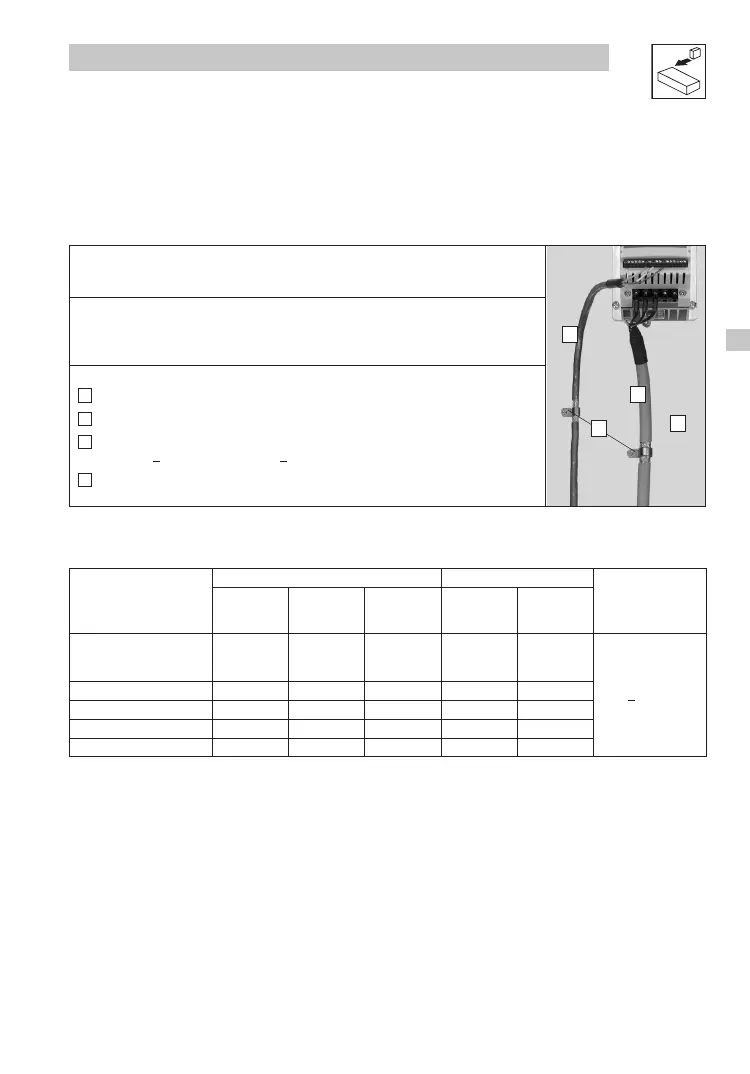
A
Screen clamps
B
Control cable
C
Low-capacitance motor cable
(core/core < 75 pF/m, core/screen < 150 pF/m)
D
Electrically conductive mounting plate
Tml005
B
C
D
A
3.2 Electrical installation
3.2.1 Installation according to EMC requirements
3.2.2 Fuses/cable cross-sections
(1)