Home
Leser
Control Unit
526 API
Page 22 (9.5.6 Inserting Spindle;Disc Assembly (With Stainless Steel Bellows))
Leser 526 API - 9.5.6 Inserting Spindle;Disc Assembly (With Stainless Steel Bellows)
45 pages
Manual
Save Page as PDF
To Next Page
To Next Page
To Previous Page
To Previous Page
Loading...
LESER Global Standard
Assembly instruc
tions for type 526 AP
I
LGS 4104
Page
22
/
45
disclosure cat.:
II
proofread:
SSt
published date:
06/14/18
effect. date:
05/18
author:
Nieh
released by:
KU
W
replaces:
initial
status:
Published
resp. depart.:
IE
date of release:
06/14/18
revision No.:
2
doc. type:
LGS
change rep. No.:
NA
retention period:
10
protected
9.5.6
Inserting the spindle/disc assembly (with stainless steel bellows)
Illustration
Description
A
ids /
Tools
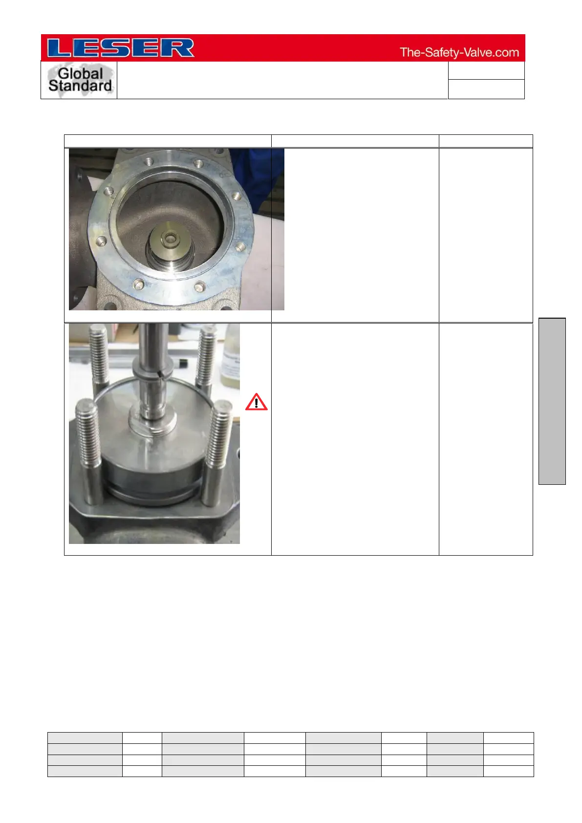
Put the sealin
g into the bod
y.
Figure 9.5.3-1
Insert the spindl
e/disc/cooli
ng
zone into the body
. In the
process, push the
guide w
asher
down and li
ft the spindle
somewhat so tha
t the disc does
not touch down.
Carefully put the
disc with the
spindle dow
n on the seat.
21
23
Table of Contents
Main Page
Table of Contents
2
Purpose
2
Scope
2
References
3
Disclaimer
3
Qualified Fitting Personnel
3
General Information
3
General Illustration
4
Preparation for Valve Assembly
5
Emboss the Punch Numbers (if Requested in the Order)
5
Assembly of Type 526
5
Assembly of the Nozzle and Blow down Ring
5
Screw the Studs into the Body
7
Installation of the Locking Screw and Screw Plug
7
Assembly of Disc Assembly
9
Assembly of Spindle/Disc Assembly
13
Assembly of the Bonnet
24
Determination and Installation of the Lift Stopper
25
Assembly of the Adjusting Screw
28
Adjusting the Set Pressure
30
Testing the Seat Tightness P12
31
Assembly of the Cap / Lever
31
Assembly of the Lift Indicator
38
Installation of the Test Gag (Possible for H2 and H4)
40
Installation of the Different O-Ring Dampers
41
Adjusting the Set Pressure
45
Testing the Seal Tightness of the Back Seal P21
45
Sealing the Valve
45