LESER Global Standard
Assembly instructions for type 526 API
9.7 Determination and installation of the lift stopper
9.7.1 Lift stopper with ring/sleeve
9.7.1.1 Procedure for small valves without bellows (up to approx. DN 65 / 2 1/2").
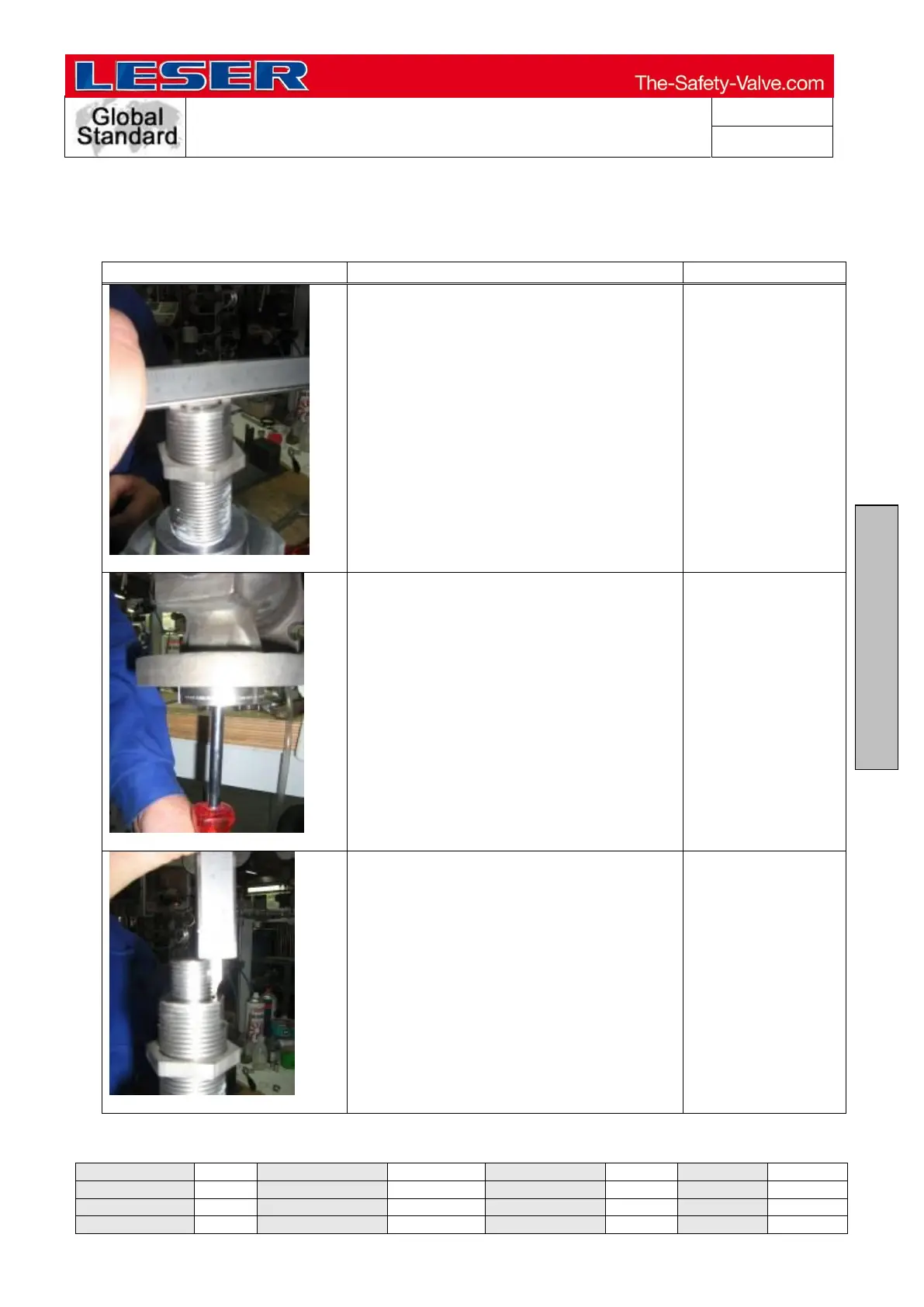
Take the extent to which the stroke has to
be limited from the work order. Insert the
spindle/disc assembly without the spring
and spring plate. Put on the bonnet and
tighten the nuts.
Make the adjusting screw and spindle
flush.
Clamp the body on the outlet in the vice.
Lift the disc with a screwdriver through
the inlet as far as it will go.
Screwdriver
Clamping block
Measure the spindle overlap in an opened
state. Deduct the requested stroke from
this measurement and have a lift stopper
made.