Mounting
Leuze electronic MLC 510 22
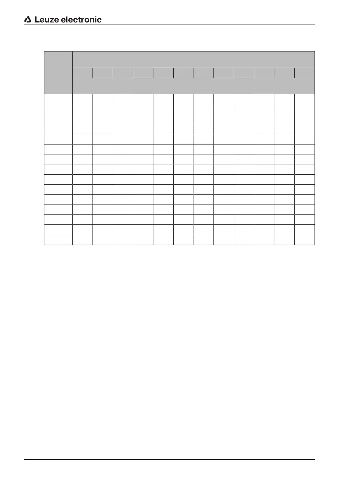
Tab.6.1: Reaching over the vertical protective field of electro-sensitive protective equipment(excerpt from
ISO13855)
Heighta
of the
point of
opera-
tion
[mm]
Heightb of the upper edge of the protective field of the electro-sensitive protective
equipment
900 1000 1100 1200 1300 1400 1600 1800 2000 2200 2400 2600
Additional distanceC
RO
to the danger zone [mm]
2600 0 0 0 0 0 0 0 0 0 0 0 0
2500 400 400 350 300 300 300 300 300 250 150 100 0
2400 550 550 550 500 450 450 400 400 300 250 100 0
2200 800 750 750 700 650 650 600 550 400 250 0 0
2000 950 950 850 850 800 750 700 550 400 0 0 0
1800 1100 1100 950 950 850 800 750 550 0 0 0 0
1600 1150 1150 1100 1000 900 850 750 450 0 0 0 0
1400 1200 1200 1100 1000 900 850 650 0 0 0 0 0
1200 1200 1200 1100 1000 850 800 0 0 0 0 0 0
1000 1200 1150 1050 950 750 700 0 0 0 0 0 0
800 1150 1050 950 800 500 450 0 0 0 0 0 0
600 1050 950 750 550 0 0 0 0 0 0 0 0
400 900 700 0 0 0 0 0 0 0 0 0 0
200 600 0 0 0 0 0 0 0 0 0 0 0
0 0 0 0 0 0 0 0 0 0 0 0 0
Depending on the specified values you can work with the above-mentioned table in three ways:
1. Given are:
• Heighta of the point of operation
• DistanceS of the point of operation from the safety sensor, and additional distanceC
RO
To be determined is the required heightb of the upper beam of the safety sensor and thereby its protective
field height.
Ä Look for the line with the specification of the point of operation height in the left column.
Ä In this line, look for the column with the next highest specification for additional distance C
RO
.
ð The required height of the upper beam of the safety sensor is up top in the column head.
2. Given are:
• Heighta of the point of operation
• Heightb of the upper beam of the safety sensor
To be determined is the required distance S of the safety sensor to the point of operation and thereby addi-
tional distance C
RO
.
Ä In the column head, look for the column with the next lowest entry for the height of the upper beam of
the safety sensor.
Ä Look for the line with the next highest specification of the point of operation heighta in this column.
ð In the intersection point of the line and the column, you will find additional distanceC
RO
.
3. Given are:
• DistanceS of the point of operation from the safety sensor, and additional distanceC
RO.
• Heightb of the upper beam of the safety sensor
To be determined is the permitted heighta of the point of operation.
Ä In the column head, look for the column with the next lowest entry for the height of the upper beam of
the safety sensor.

 Loading...

