Electrical connection
Leuze electronic MLC 510 36
Tab.7.3: Pin assignment receiver
Pin Core color (CB-M12-xx000E-5GF) Receiver
1 Brown VIN1 - supply voltage
2 White OSSD1 - safety-related switching output
3 Blue VIN2 - supply voltage
4 Black OSSD2 - safety-related switching output
5 Gray FE - functional earth, shield
Wired in device interior on the housing
FE FE - functional earth, shield
The polarity of the supply voltage selects the transmission channel of the receiver:
• VIN1=+24V, VIN2=0V: transmission channelC1
• VIN1=0V, VIN2=+24V: transmission channelC2
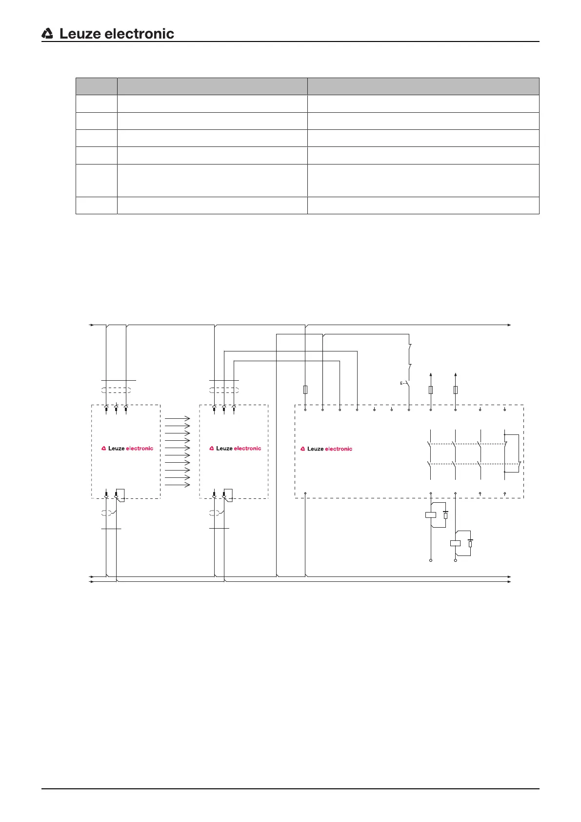
7.2 Circuit diagram examples
7.2.1
MLC510 circuit diagram example
MLCx10R
VIN1
VIN1
RNG
OSSD2
MLCx00T
OSSD1
VIN2
FE
FE
VIN2
4
BN
BK
WH
-A1
1 2
3
4
-A2
1 2
3
BN
BK
-W1
-W2
5
-W2
GY
BU
-W1
5
GY
BU
0V
PE
+24V
PE
+24V
0V
n.c.
14 24 42
13 23 41
A1
A2
-K3
1
2
1
2
L+ L+
L- L-
-S1
-K3
-K4
+24V
0V
MSI-SR4B
A1
-A3
A2
S22 S12 S31 S33 S34 S35
2 AOPD-
1 AOPD+
33
34
A1
A2
-K4
2 AOPD+
IV-0
RES-0
RES-I
1
2
*
*
Fig.7.4: Circuit diagram example with downstream MSI-SR4B safety relay

 Loading...

