Mounting
Leuze electronic MLC 510 26
6.1.5
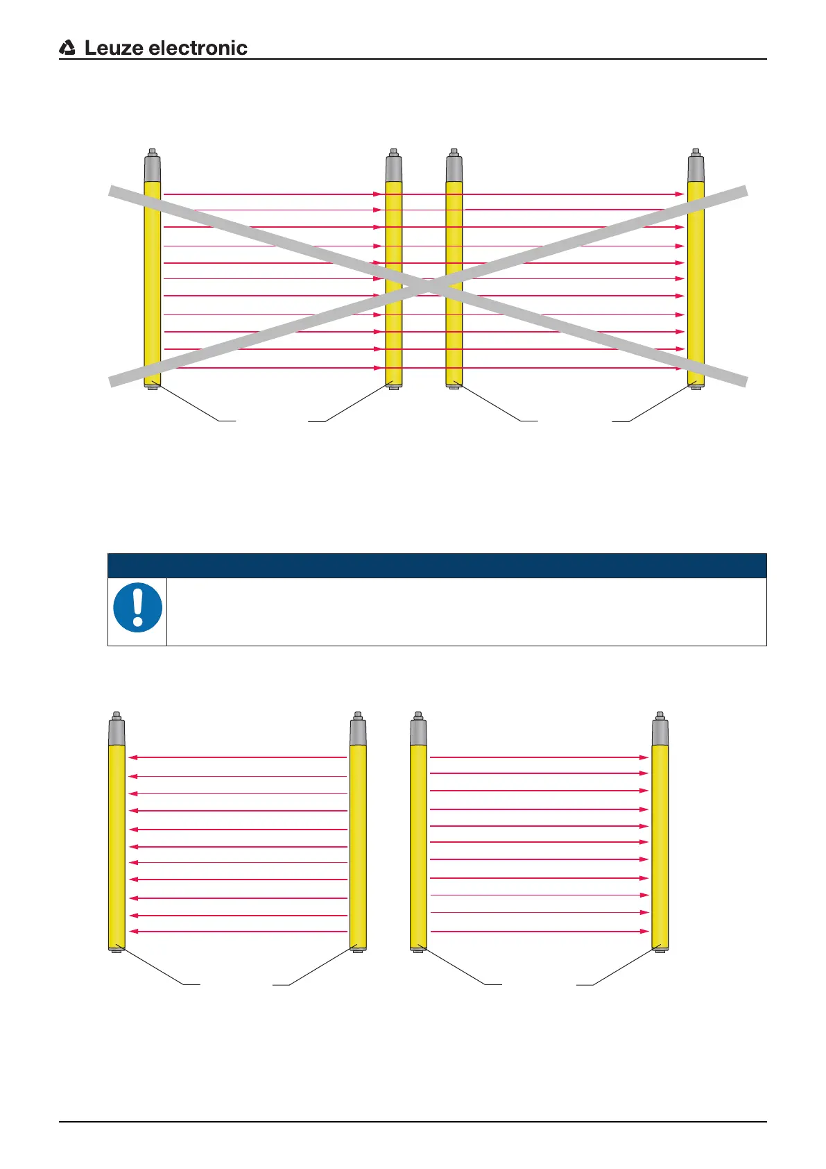
Preventing mutual interference between adjacent devices
If a receiver is located in the beam path of an adjacent transmitter, optical crosstalk, and thus erroneous
switching and failure of the protective function, may result.
Fig.6.4: Optical crosstalk between adjacent safety sensors (transmitter1 influences receiver2) due to incorrect
mounting
1 Transmitter1
2 Receiver1
3 Transmitter2
4 Receiver2
NOTICE
Possible impairment of the availability due to systems mounted close to each other!
The transmitter of one system can influence the receiver of the other system.
Ä Prevent optical crosstalk between adjacent devices.
Ä Mount adjacent devices with a shield between them or install a dividing wall to prevent mutual interfer-
ence.
Ä Mount the adjacent devices opposite from one another to prevent mutual interference.
Fig.6.5: Opposite mounting
1 Receiver1
2 Transmitter1
3 Transmitter2
4 Receiver2

 Loading...

