Troubleshooting
Leuze electronic MLC 510 45
11 Troubleshooting
11.1 What to do in case of failure?
After switching the safety sensor on, the display elements (see chapter 3.3 "Display elements") assist in
checking the correct functionality and in faultfinding.
In case of failure, you can determine the fault from the LED displays or read a message from the 7-seg-
ment display. With the error message you can determine the cause of the error and initiate measures to
rectify it.
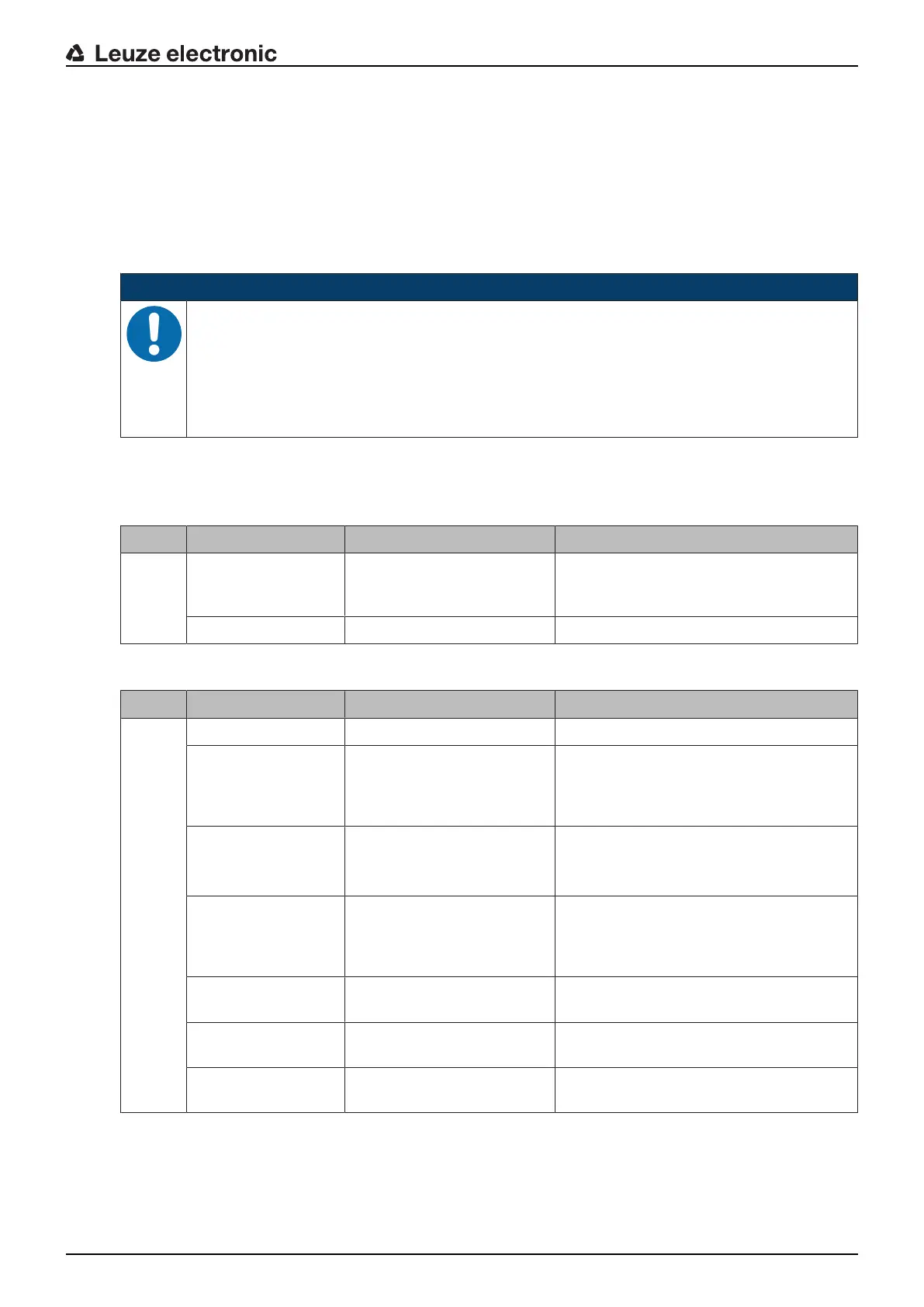
NOTICE
If the safety sensor responds with an error display, you will often be able to eliminate the
cause yourself!
Ä Switch off the machine and leave it switched off.
Ä Analyze and eliminate the cause of the fault using the following table.
Ä If you are unable to rectify the fault, contact the Leuze electronic branch responsible for you
or call the Leuze electronic customer service (see chapter 13 "Service and support").
11.2 Operating indicators of the LEDs
Tab.11.1: LED indicators at the transmitter - causes and measures
LED State Cause Measure
LED1 OFF Transmitter without supply
voltage
Check the power supply unit and the elec-
trical connection. Exchange the power
supply unit, if applicable.
Red Device failed Replace the device.
Tab.11.2: LED indicators at the receiver - causes and measures
LED State Cause Measure
LED1 OFF Device failed Replace the device.
Red Alignment incorrect or pro-
tective field interrupted
Remove all objects from the protective
field. Align the transmitter and receiver to
each other or place blanked objects cor-
rectly concerning size and position.
Red
(LEDs on transmitter:
both green)
Receiver is set on C1,
transmitter on C2
Set the transmitter and receiver on the
same transmission channel and align both
correctly.
Red
(LED1 on transmitter:
green)
Receiver is set on C2,
transmitter on C1
Remove all objects from the protective
field. Align the transmitter and receiver to
each other or place blanked objects cor-
rectly concerning size and position.
Red, flashing slowly,
approx.1Hz
External error Check the connection of the cables and
the control signals.
Red, flashing fast,
approx.10Hz
Internal error If restart fails, exchange the device.
Green, flashing
slowly, approx.1Hz
Weak signal due to contami-
nation or poor alignment
Clean the front screens and check the
alignment of transmitter and receiver.

 Loading...

