4.1.6 Installation of RS485 Fieldbus Multi-Pump System Arrays
Figure 16 shows a multi-pump system arrangement with the RS485 fieldbus and its basic specifications.
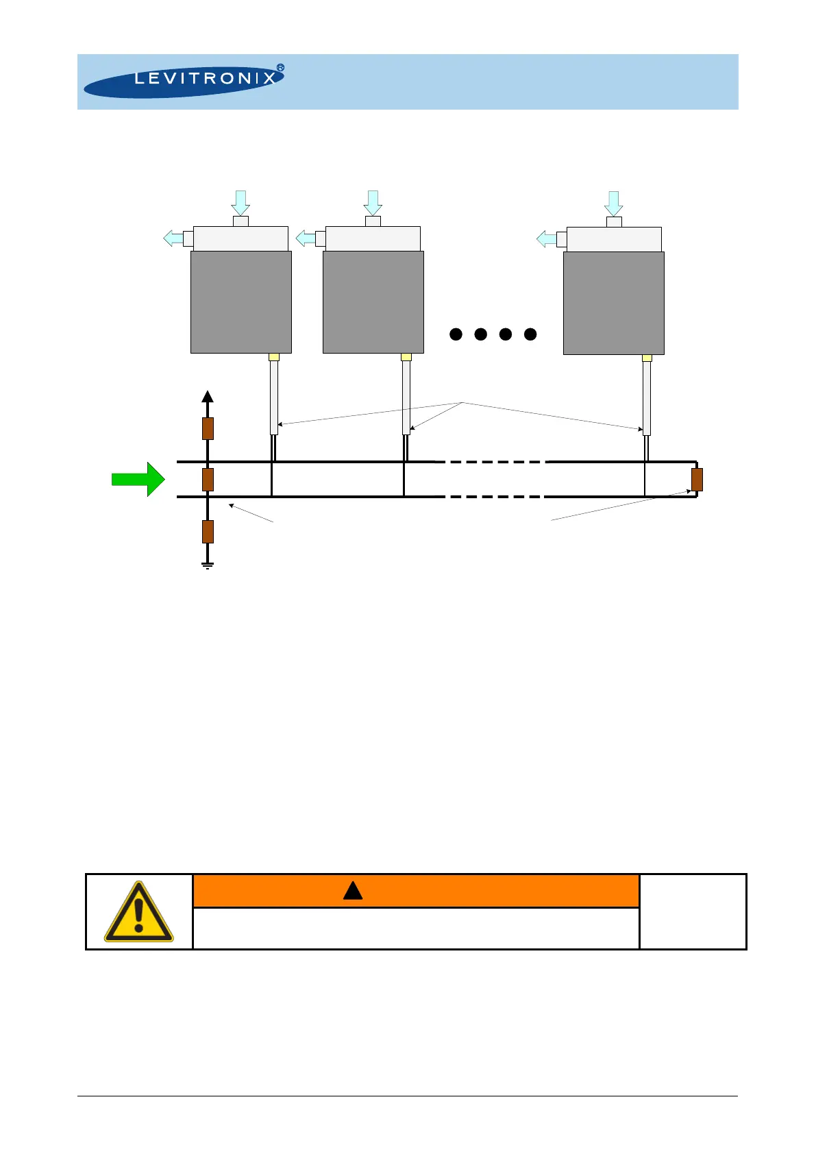
Figure 16: Multi-pump system arrangement with RS485 fieldbus
Following points and information shall be considered:
➔ Testing has been done with arrangements of 8 pump systems. Higher number is possible but it is
recommended to contact Levitronix
®
Technical Service department (see Section 8) for details and support.
➔ Address setting of the pump units can be done with the Levitronix
®
Service Software and a PC. A USB/RS485
converter cable with integrated initialization network can be ordered according to Table 3.
➔ The RS485 protocol for master communication is available at Levitronix
®
on request.
➔ Do not use multiple master systems at the same time.
➔ Do not use closed ring arrangements.
4.2 Mechanical Installation
4.2.1 Mechanical Installation of Driver and Pump Head
The driver can be fixed with four screws on the motor feet (see Figure 7). Mounting can be done in either in
horizontal or vertical position. When mounting the pump head fittings into a circuit, care shall be taken that no
mechanical stress is acting on the fittings, which can result in distorting creeping effects.
4.2.2 Mechanical Installation of Water Cooling Module
The water cooling module WCM-600.1 can be mounted to the driver top as illustrated in Figure 8. The cooling
liquid (for example water) can be connected over the two NPT 1/8” fittings (see Figure 8). A minimum cooling
liquid flow of 0.5 l/min at @ ≤ 20°C temperature is recommended.
120W120W
510W
510W
Master
Integrated
System
#1
Integrated
System
#2
Integrated
System
#N
5V
Branch Bus Lines:
Length sum of all < 33m.
Main Bus Line: < 100m
Shielded cable with drilled wires recommended.
Termination:
Recommended for main bus line Length > 5m.
Initialization Network:
Always recommended.
To be implemented at the master.