User Manual for LCO-i100 Console
www.levitronix.com
PL-4066-00, Rev03, DCO# 21-230
Isolation with optocoupler. 350 Ω input resistance.
The designation can be changed in PLC Interface Settings
on the Console touch screen (see LCO Console Software
Manual PL-4067-00). Options are Flow Setpoint and
Pressure Setpoint.
24 V On
(rotating and levitating)
0 V Off
(not rotating and not levitating)
Isolation with optocoupler. Input resistance 2.2 kΩ.
Typical 24 V / 10 mA. Minimum for level detection is 5 V
(2 mA) and max. 30 V (13 mA).
The designation can be changed in the PLC Interface
Settings on the Console touch screen (see LCO Console
Software Manual PL-4067-00). Options are Flow Control
On/Off and Pressure Control On/Off. Furthermore, the
logic can be inverted.
24 V (min. 5V) active
0 V not active
Isolation with optocoupler. Input resistance 2.2 kΩ.
Typical 24V / 16mA. Minimum for level detection is 5V
and max. 30V (20mA).
Is for example needed to clear an Error.
Digital Output 1
High Pin
Open pump disabled.
Closed pump enabled.
Isolated relay with max. 30 VDC / 1 A.
The designation can be changed in the PLC Interface
Settings on the Console touch screen (see LCO Console
Software Manual PL-4067-00). Options are to invert the
logic and to permanently open or close the relay.
Option: Can be switched by software to 24VDC output with
max load of 750 mA (PTC fuse non-isolated).
3
Digital Output 2
High Pin
Open no error.
Closed error of pump.
Isolated relay with max. 30 VDC / 1 A.
The display gives notifications with more details to the
background and potential mitigations (see LCO Console
Software Manual PL-4067-00 for more details).
Option: Can be switched by software to 24VDC output
with max load of 750 mA (PTC fuse non-isolated).
3
Isolation with optocoupler. External 24 V source with load
shunt between 33-750 Ω is needed.
The designation can be changed in PLC Interface Settings
on the Console touch screen (see LCO Console Software
Manual PL-4067-00). Options are Actual Flow and Actual
Pressure.
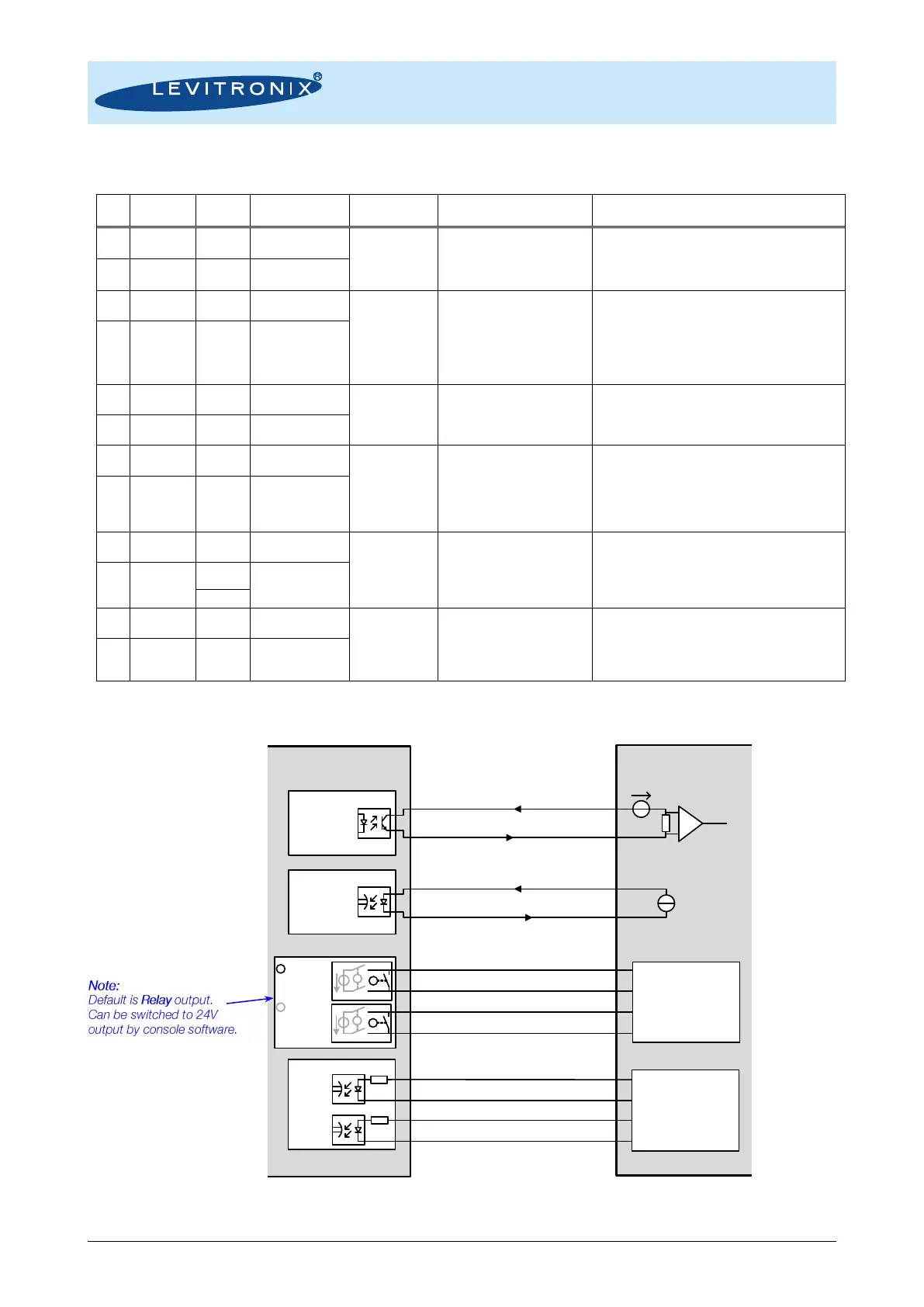
Table 10: PLC connector of Console
1: Wires of compatible cables: ICS-2.1-xx 2: Designations are for standard firmware. Note 3: Not available on units older than 2018/19.
Figure 10: Connection example of PLC interface of Console to user interface
Levitronix Console
PLC Interface Circuit
11: Analog Out High Pin
12: Analog Out Low Pin
1: Analog In High Pin
2: Analog In Low Pin
3: Digital In 1 High Pin
4: Digital In 1 Low Pin
5: Digital In 2 High Pin
6: Digital In 2 Low Pin
4..20 mA
Relay
with max.
30VDC/1A
7: Digital Out 1 High Pin
8: Digital Out 1 Low Pin
9: Digital Out 2 High Pin
10: Digital Out 2 Low Pin
24 VDC
4..20 mA
Digital Input
Digital Output
33-750 Ω
equiv. 350 Ω
2.2 kΩ
24 VDC / 10 mA
2.2 kΩ
Example of User Interface
2
1
24 VDC
GND
2
1
DC Out
24 VDC
with max.
750mA
2
1
24 V
GND
 Loading...