Do you have a question about the Levitronix PuraLev i100SU and is the answer not in the manual?
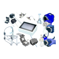
Detailed specifications of individual system components and accessories.
Illustrates the system configuration for the Stand-Alone model.
Details the system configurations available for the EasyConnect model.
Explains the system configurations designed for OEM integration.
Details system configuration for OEM models in ATEX/IECEx classified areas.
Details power requirements and consumption for the pump system.
Explains how the system monitors temperature and reacts to overheating.
Outlines the electrical connection process for the Stand-Alone driver.
Identifies and describes connections and designations for the EasyConnect driver.
Lists wire designations and colors for the OEM driver cable.
Details manual operation of the Stand-Alone model using the user panel.
Details operating EasyConnect and OEM models via PLC interface.
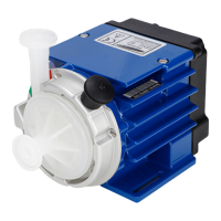
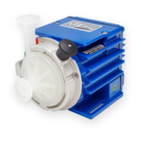
Describes the DCP-200 pump heads and their preparation for use.
Lists general warnings and cautions related to handling the pump head.
How to troubleshoot the Stand-Alone model using its display and signals.
Troubleshooting EasyConnect and OEM models with driver signals.
Details using the Levitronix Service Software for detailed troubleshooting.
Declares conformity with relevant European directives and standards.
Explains ATEX/IECEx certification and marking for pump drivers.
Lists biocompatibility specifications for the pump heads (FDA, USP VI).
| Brand | Levitronix |
|---|---|
| Model | PuraLev i100SU |
| Category | Water Pump |
| Language | English |