Do you have a question about the Levitronix PuraLev iF100SU and is the answer not in the manual?
Covers cautions for magnetic fields, hazardous voltage, and toxic chemicals.
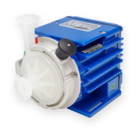
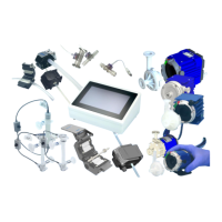
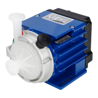
Details of main components, drivers, and pump heads with part numbers.
Description of system configurations for Stand-Alone, EasyConnect, and OEM models.
Specifies operating and storage conditions like temperature and humidity.
Illustrates pressure vs. flow rate characteristics at different RPMs.
Details max static pressure limits for pump heads based on temperature.
Lists flow range, accuracy, and response time for flow controllers.
Provides physical dimensions for main components of Stand-Alone and EasyConnect models.
Details electrical power requirements, consumption, and inrush currents.
Explains system temperature monitoring and overheating protection.
Illustrates driver temperature characteristics based on liquid and ambient temperatures.
Provides guidelines for optimal hydraulic circuit design for efficiency and priming.
Details electrical connections for the Stand-Alone driver model.
Details electrical connections for the EasyConnect driver model.
Instructions for connecting PLC signals to the EasyConnect model.
Information on using RS485 for control and service on EasyConnect models.
Details multi-system RS485 fieldbus arrangements for EasyConnect models.
Details electrical connections for the OEM driver model.
Instructions for installing power supply for OEM model.
Instructions for connecting PLC signals to the OEM model.
Instructions for installing and connecting the flow sensor.
Instructions for mechanically mounting the driver and pump head.
Details the mechanical installation of the flow sensor and its ideal positioning.
Describes manual operation of the Stand-Alone model using its user panel.
Explains navigation and functions within the Stand-Alone model's system menu.
Describes operation of EasyConnect and OEM models via PLC interface.
Explains how to perform zero adjustment for the flow sensor on different models.
Introduces the DCP-200 pump heads and their preparation for use.
Details inspection prior to use and traceability via serial numbers.
Step-by-step guide for mounting the pump head onto the driver.
Step-by-step guide for removing the pump head from the driver.
Guidance for troubleshooting the Stand-Alone model using its display.
Troubleshooting for EasyConnect/OEM using PLC signals or software.
Details CE marking, directives, and standards compliance.
Information on biocompatibility of wet materials according to FDA and USP standards.
Explains safety symbols, signal words (DANGER, WARNING, CAUTION), and their meanings.
| Pump Type | Centrifugal |
|---|---|
| Flow Rate | Up to 100 L/min |
| Fluid Temperature | 5°C to 40°C |
| Operating Temperature | 5°C to 40°C |
| Voltage | 24 V DC |
| Materials (Wetted) | Ceramic |
| Connectivity | Analog/Digital |
| Weight | 2.5 kg |
| Material | Polypropylene |
| Motor Technology | Magnetically Levitated Motor |