4.3.7 Installation of RS485 Fieldbus Multi-System Arrays
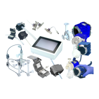
Figure 25 shows a multi-pump system arrangement with the RS485 fieldbus and its basic specifications.
Figure 25: Multi-pump system arrangement with RS485 fieldbus
Following points and information shall be considered:
➔ Testing has been done with arrangements of 8 systems. Higher number is possible but it is recommended to
contact Levitronix
®
Technical Service department (see Section 8) for details and support.
➔ Address setting of the pump units can be done with the Levitronix
®
Service Software and a PC. A USB/RS485
converter cable with integrated initialization network can be ordered according to Table 4.
➔ The RS485 protocol for master communication is available at Levitronix
®
on request.
➔ Do not use multiple master systems at the same time.
➔ Do not use closed ring arrangements.
4.4 Electrical Installation of Flow Sensor
1. Every sensor comes delivered with a calibration sheet. Check if the S/N on the calibration sheet corresponds to the
S/N on the type label of the sensor.
2. Please store the delivered calibration sheet or its data on a defined storage place in order to be able to refer to it in
case of problems.
3. Attach one of the sensor extension cables (Table 4, Position 9a) coming from the driver to the sensor connector.
4. When applying power, the flow control drivers needs about 10 seconds for a start-up procedure to be ready. In
order to get stable temperature and signals for flow converter and sensor 30 minutes shall be waited after power-
on.
5. After start-up a Zero adjustment is recommended as described in Section 4.6.