User Manual for PuraLev
®
iF100SU
www.levitronix.com
PL-4079-00, Rev00, DCO# 21-271
4.3 Electrical Installation of OEM Model
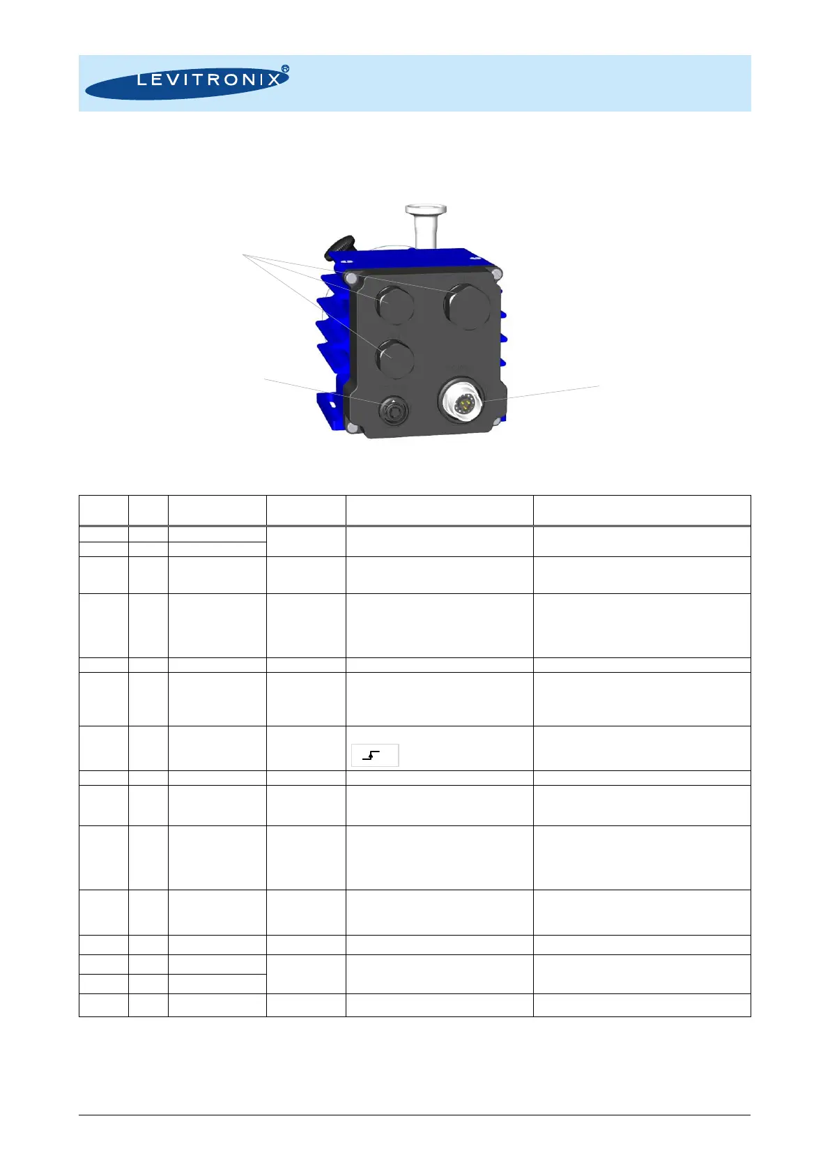
4.3.1 Overview Wire Designation of Driver Cable
Figure 23: Electrical connections to OEM flow control driver IFD-100.4
P- to be connected to earth.
Analog Input 1
(Current Input)
Reference Value
(Set Flow or
Speed)
4..20 mA = 0..100% of full scale (flow control)
4..20 mA = 0..10000 rpm (speed control)
Speed limit = 9000 rpm, Cutt-off speed = 0 rpm
450 Ohm shunt input, no galvanic isolation.
The designation of the analog inputs can be changed
with Levitronix
®
Service Software.
Analog Input 2
(Voltage Input)
Configurable as
setpoint input
Analog voltage input: 0 – 10V
(7.9 kOhm, no galvanic isolation).
Note: Max. input voltage of 11 V shall not be
exceeded.
The designation of the analog inputs can be changed
with Levitronix
®
Service Software.
Reference for analog inputs.
5-24 V active
0 V not active
Galvanic separation with optocoupler and
2.2 k input resistance.
The “Enable” signal switches the flow control system
on and off. Resets pump from error state with 300-
700ms pulse.
Galvanic separation with optocoupler and
2.2 k input resistance.
Triggers a Zero Adjust of the flow sensor. Duration of
Zero Adjust process is about 5 seconds.
Analog Output
(Voltage Output)
0..10 V = 0..100% of full scale flow
Direct connection, no protection. Galvanic isolation on
user side is required. GND is reference.
The configuration of the analog output can be changed with
Levitronix
®
Service Software.
Closed circuit active, pump running
Open circuit not active, system off or error
Open drain, max. 24V, 100mA
This signal indicates the state of the flow control
system. If not active, pump is either in “Off” or in
“Error” state.
The configuration of the digital outputs can be
changed with Levitronix
®
Service Software.
Closed circuit active, measurement o.k.
Open circuit not active, measure. error
Slow blinking (2 Hz) Zero Adjust error
Fast blinking (10 Hz) Zero Ad. in progress
Open drain, max. 24V, 100mA
The configuration of the digital outputs can be changed
with Levitronix
®
Service Software.
Reference for Aout1, Dout1 and Dout2
Termination resistors recommended
To be connected to earth
(see wire P-, black)
Table 15: Signals of the driver cable with designation for standard firmware
Note 1: For other configurations of PLC Inputs and Outputs refer to alternate firmware documentation
Note 2: Configurations can be done with Levitronix
®
Service Software
Note 3: Power wires (P+, P-) have cross section 1.5 mm
2
and all others 0.14 mm
2
Not configured
connections.