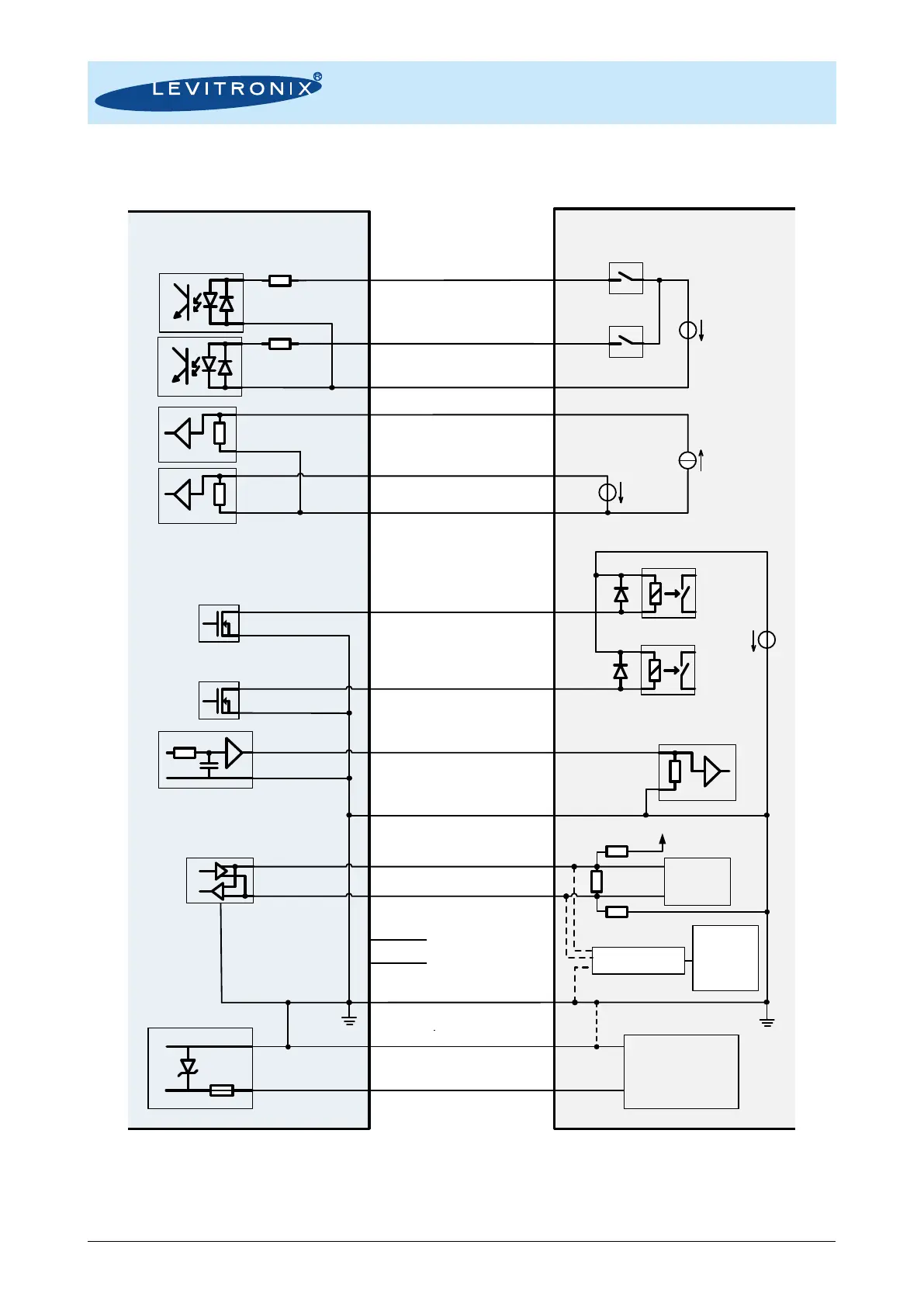
4.3.2 Overview Electrical Schematics of OEM Driver Interface
Figure 25: Electrical schematics of interfacing for OEM driver model
Note 1: RS485/USB converter cable with termination resistors to be ordered according to Table 3.
Note 2: Do not use multiple master devices on the RS485 at the same time.
Levitronix Driver
Interface Circuit
Example of User
Interface Circuit
450
7.9 k
GND
2.2 k
2.2 k
Brown: Digital Output 1
White: Digital Output 2
Yellow: Common Digital Input
Grey: Digital Input 2
Pink: Digital Input 1
Blue: Analog Input Ground
Violet: Analog Input 1
Grey-Pink: Analog Input 2
White-Green:
Analog Ground (GND)
Blue-Red: Analog Output
Brown-Green: RS485+
White-Yellow: RS485-
Yellow-Brown: Do not connect
White-Grey: Do not connect
Cable Shield
Relais
GND
4..20 mA
0..10 V / 2 mA
RS485/USB Cable
with Termination
Personal
Computer
(Service)
24 V
5..24 V
0..10 V
R > 5 k
Analog inputs are not galvanic isolated.
Max. pin voltage to GND = 10 V
Max. 24 V / 100 mA
Max. 24 V / 100 mA
Open
Drain
Open
Drain
R > 240
R > 240
Relais
Cable Wires (UL Cable)
Colours/Designation
R = 510
Tool
Control
R = 510
AC/DC Supply
24 VDC
Red: 24 VDC
Black: Ground/Earth
R = 120
+5 V
30 V
5 A