5 Operation
5.1 Operation of Stand-Alone Model
5.1.1 Manual Operation
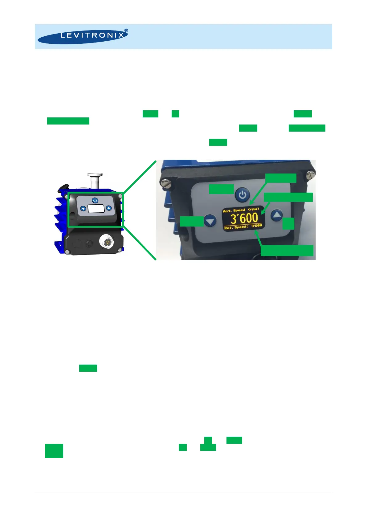
With the Stand-Alone model the system can be operated manually with the user panel according to Figure 28.
The speed can be set manually with the Down and Up buttons before or after enabling it with the On/Off button.
The Setpoint Speed (= Ref. Speed) is then stored in the system EEPROM and will stay the same, even if the
system is powered off. When disabling the system by shortly pressing the On/Off button the Actual Speed is
first reduced to zero before an impeller touch down is made by disabling the radial levitation. After an Error
(see details in Section 5.1.4) the system can be restarted by the On/Off button or by removing and reattaching
the power supply.
Figure 28: User panel of stand-alone model for manual operation
5.1.2 Operation with PLC
When activating the digital input on the PLC connector the speed can be set with an analog signal (see Table
8 for hardware details). The Status of the system can be monitored with a digital output signal. During analog
speed control all information is shown on the display.
5.1.3 Extended Menu Functions
By pressing the On/Off button for more than 4 seconds an extended Menu can be reached, which allows
a. Monitoring of system parameters like driver temperature, axial position of rotor, supply
voltage (DC-link voltage), bearing phase currents (BNG) and drive phase currents (DRV).
b. Reading of error, warning and message information and their history.
c. Reading of firmware version.
d. Setting a timer.
In the extended Menu, the menu tabs are browsed using the Up and Down buttons. Items are selected with
the On/Off button, and values are modified using the Up and Down buttons. The Menu can be left by pressing
the On/Off button for more than 2 seconds.