User Manual for PuraLev
®
i100SU
www.levitronix.com
PL-4063-00, Rev03, DCO# 20-275
4 Installation
4.1 Electrical Installation of Stand-Alone Model
4.1.1 Overview of Connections and Designations
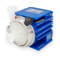
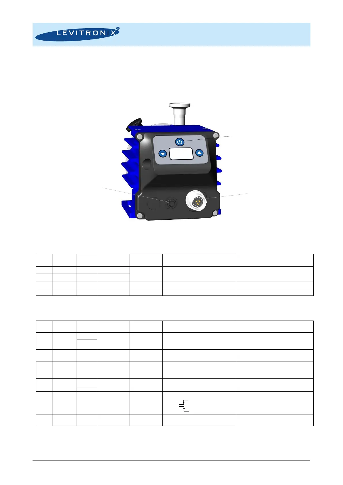
Figure 20: Electrical connections to Stand-Alone driver
Specifications
Typical Levels
Voltage: 24 VDC ±10%
Power: 110 W
“P -“ shall be connected to earth
Wire of compatible cables is cut.
Wire of compatible cables is cut.
Wire of compatible cables is cut.
Wire of compatible cables is cut.
Table 7: Power supply connector of Stand-Alone driver
1: Wire colors of compatible cables: ICP-2.1-xx. 2: Designations for standard firmware. For other firmware refer to relevant documentation.
4..20 mA = 0..10000 rpm
-> Speed limit = 9000rpm
-> Cut-off (min.) speed = 0 rpm
450 Ohm shunt input, no galvanic isolation.
Closed circuit active, system on
Open circuit not active, system off
Open drain, max. 24V, 100mA
This signal indicates the state of the pump
system.
Edge triggered:
0 V 5-25 V Enable
5-25 V 0 V Disable
For enabling of the system with external signal.
Galvanic separation with optocoupler and
2.2 k input resistance.
Table 8: PLC connector of Stand-Alone driver
1: Wires of compatible cables: ICS-1.1-xx and ICS-1.2-xx.
2: Designations for standard firmware. For other firmware refer to relevant documentation.