User Manual for PuraLev
®
i100SU
www.levitronix.com
PL-4063-00, Rev03, DCO# 20-275
4.2.3 Installation Instructions for Power Supply
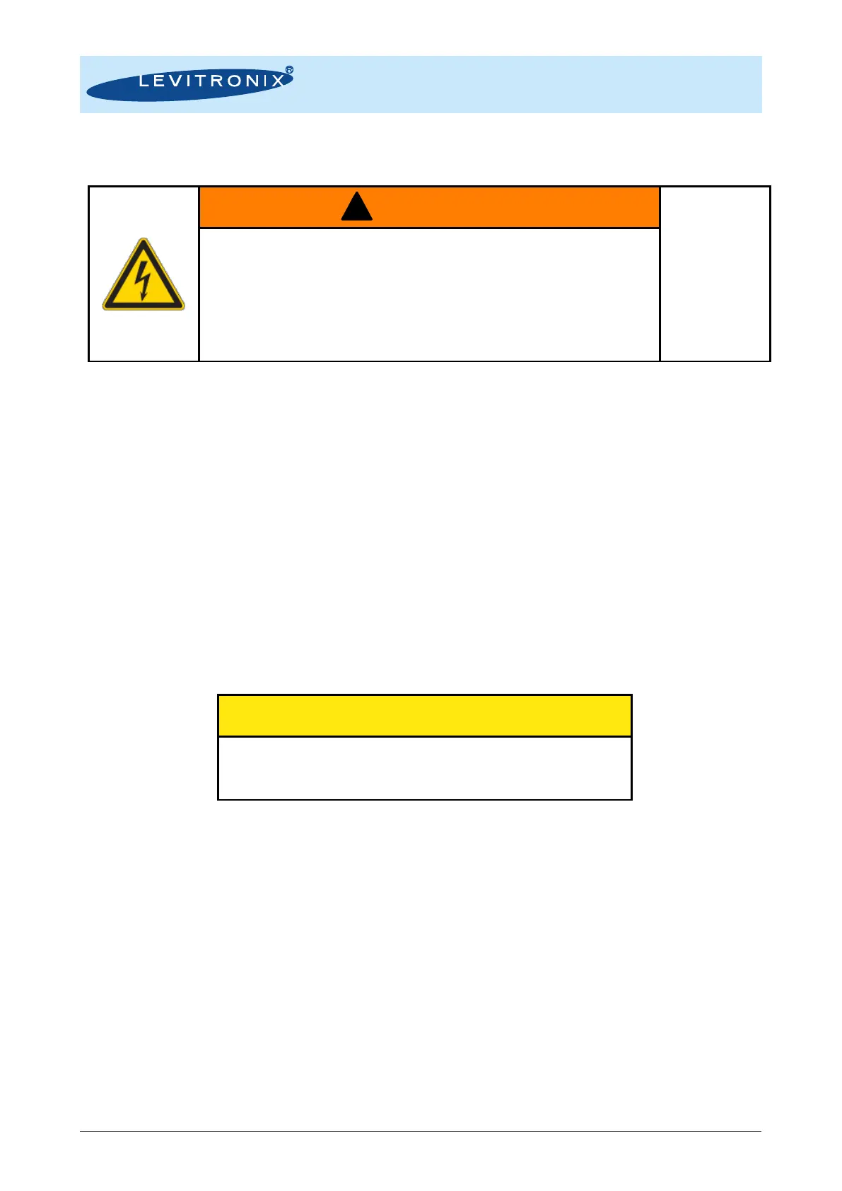
Hazardous voltage may be present.
Always isolate the electrical power supply before making or changing
connections to the unit.
In case of the usage of an inadequate AC/DC power supply, mains
voltages may be present (even if the system is designed for 24 VDC).
The usage of a galvanic separated power supply, which is certified by a
3
rd
party (UL or CE), is highly recommended.
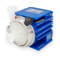
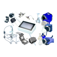
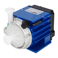
1. Certified and tested power supplies (desktop and DIN rail version) are available as an accessory
(see Table 3).
2. For other power supplies an open wire power cable for connection to the driver is specified in
Table 3 (cable type ICP-2.1). Depending on the required hydraulic operational point (see Figure
11), the pump system requires 24 VDC with a maximum power of 110 W. At a lower performance
power supplies with smaller power or bigger supplies to supply several pump systems
simultaneously may be used. Consult Figure 17 to get the power consumption depending on the
flow. If other power supplies are used than the one recommended by Levitronix
®
, it is highly
recommended to test these under dynamic conditions (acceleration and braking of the pump rotor
speed).
3. Make sure that the polarity is correct and that AC/DC power supply is off.
4.2.4 Installation PLC Interface Signals
To operate the pump system with a PLC the analog input can be used to set either the speed or the process
value (flow or pressure). The digital and analog outputs can be used to monitor the pump status and operating
parameters (see Table 12).
The analog inputs and outputs are not galvanically isolated from
the controller electronics. To avoid ground loops and mal-
functions, use floating analog signals.
1. Power off the system.
2. A signal cable with driver connector is available to simplify PLC wire connections (see Table 3
cable type ICS-2.1). Connect the designated PLC wires according to Table 12.
3. Follow Figure 25 of the OEM model as reference for hardware configuration of the PLC in/outputs.
4. Protect the un-used wires against short-circuit to each other.
4.2.5 Installation Fieldbus Interfaces
For usage of the RS485 (Fieldbus IN) as a control or service interface, an initialization resistor network
according to Figure 22 shall be used in order to have a stable communication and avoid disturbance effects.
The RS485 protocol for master communication is available at Levitronix
®
on request.
For Service and Debugging purposes with the Levitronix
®
Service Software and PC a USB/RS485 converter
cable with integrated initialization resistors can be ordered according to Table 3. Do not use multiple master
devices at the same time.
The Fieldbus OUT interface can be used to feed through the RS485 bus to other devices.