Lexicon
4-27
7. Press the Yes button once. The display reads: Devel DSP L Sw. Turn the Knob CCW to set it to Nrm10.
8. Press the Yes button once. The display reads: Devel Mix Switch. Verify that it is set to Off 0.
9. Press the Yes button 4 times. The display reads: Devel SpkSp On 1. Turn the knob CCW to set it to
Byp 0.
10. Press the Yes button 4 times. The display reads: Devel SpkrSim BP. Turn the knob CCW to set it to
Byp 0.
11. Press the Yes button 5 times. The display reads: Devel Bass. Verify that it is set to 0.
12. Press the Yes button once. The display reads: Devel Trebl. Verify that it is set to 0.
13. Press the Yes button 3 times. The display reads: Devel GTone. Turn the knob CCW to set it to Byp 0.
14. Press the Yes button 3 times. The display reads: Devel Gain. Turn the knob CCW to set it to Byp 0.
15. Press the Yes button 2 times. The display reads: Devel Send. Verify that it is set to Gn 0.
16. Connect an audio input cable between the Low Distortion Oscillator and the MPX G2 Rear Guitar Input
jack.
17. Connect an audio output cable from the Left Main 1/4 Output jack on the rear of the MPX G2 to the
Distortion Analyzer.
Signal Level:
1. Apply a 1kHz-sinewave signal at +1dBu (870 Vrms).
2. Verify an output level reading between 27.29 to 25.14 dBu (18 TO 14 Vrms).
3. Switch the cable from the Left Main Output jack to the Right Main Output jack.
4. Verify an output level reading between 27.29 to 25.14 dBu (18 TO 14 Vrms).
Frequency Response Measurement:
1. Disable all Filters on the Distortion Analyzer.
2. Apply a 1kHz-sinewave signal at +1dBu (870 mVRMS).
3. Set the Analyzer for a 0dB reference.
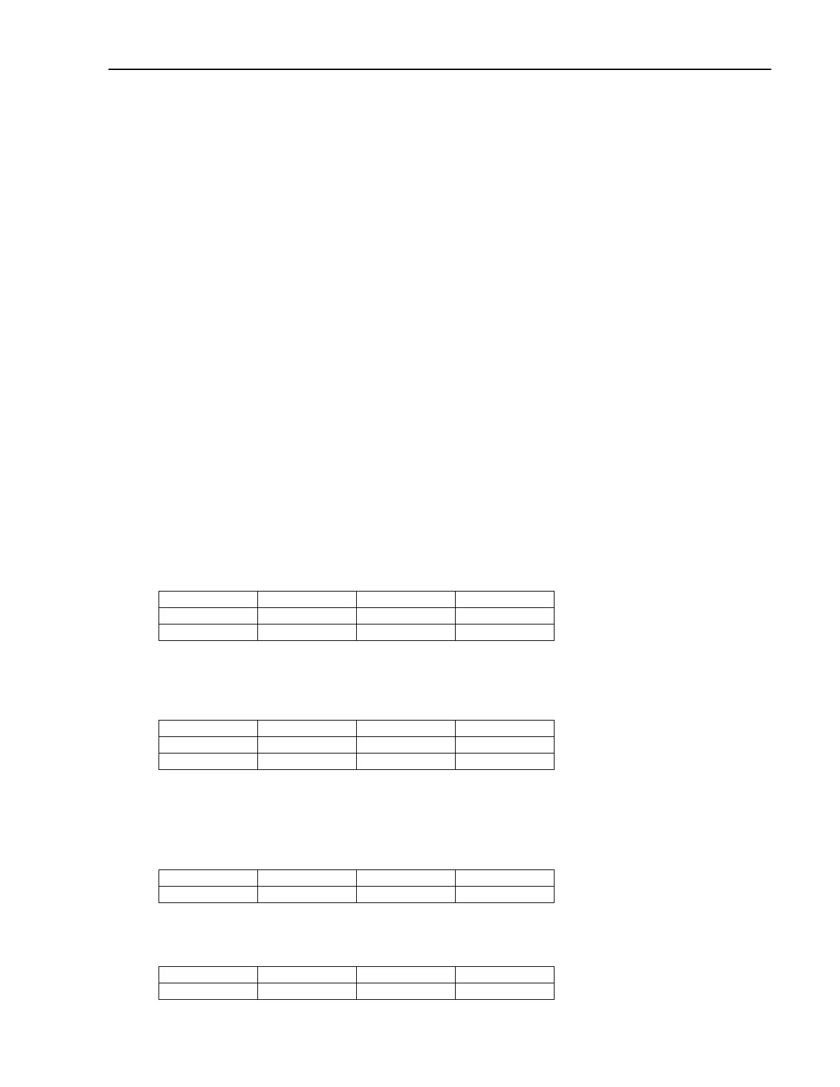
4. Verify the output level reading is between 2.06 to -3.06 dBu (1to .545 Vrms) at the following frequency
settings.
20,000Hz 16,000Hz 12,000Hz 10,000Hz
4,000Hz 2,000Hz 250Hz 100Hz
60Hz 20Hz
5. Move the cable from the Right Main Output jack to the Left Main Output Jack.
6. Verify the output level reading is between 2.06 to -3.06 dBu (1to .545 Vrms) at the following frequency
settings.
20,000Hz 16,000Hz 12,000Hz 10,000Hz
4,000Hz 2,000Hz 250Hz 100Hz
60Hz 20Hz
THD+N Measurement:
1. Set the Analyzer to measure THD+N.
2. Enable the Lo pass filters on the analyzer (30kHz or 20kHz).
3. Verify an output THD+N reading is between (0.01 to 0.0007%) at the following frequency settings.
20,000Hz 15,000Hz 10,000Hz 5,000Hz
3,000Hz 997Hz 100Hz 20Hz
4. Switch the cable from the Left Main Output jack to the Right Main Output jack.
5. Verify an output THD+N reading is between (0.01 to 0.0007%) at the following frequency settings.
20,000Hz 15,000Hz 10,000Hz 5,000Hz
3,000Hz 997Hz 100Hz 20Hz