58D6056 15
V
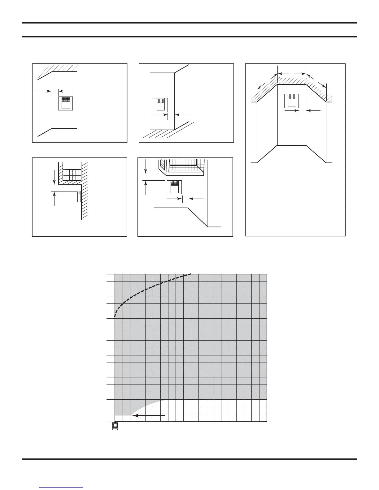
G G=6" (152mm)
F
F=6" (152mm)
V
V
G
G = Combustible 24"(610mm)
Noncombustible 18"(457mm)
Combustible &
Noncombustible
H = 24" (610mm)
J = 20" (508mm)
V
H
J
C = Maximum depth of 48" (1219mm)
for alcove location
D = Minimum width for back wall of
alcove location
Combustible - 38" (965mm)
Noncombustible - 24" (610mm)
E = Clearance from corner in alcove
location
Combustible - 6" (152mm)
Noncombustible - 2" (51mm)
E
V
D
C
C
Inside Corner
Alcove Location
Outside Corner
Balcony with No Side Wall Balcony with Perpendicular
Side Wall
Actual Stove Height
DV20 = 23
1
/
2
"
DV30 = 28
3
/
2
"
DV40 = 30
1
/
2
"
2
0
4
6
8
10
12
14
16
18
20
22
24
26
28
30
32
34
36
38
40
1234567891011 121314151617181920
HORIZONTAL RUN 20' MAX (6.1m)
VERTICAL HEIGHT 40' MAX (12.2m)
(MEASURED FROM STOVE TOP)
Minimum Height fro
Stove Top
DV20 = 18"
DV30 = 30"
DV40 = 30"
NOTE: Any vent configurations within
the shaded areas are acceptable.
Use Restrictor
Disk Above
Dotted
Line
Minimum Height from Stove Top 18"
VENT INSTALLATION
TERMINATION CLEARANCES FOR BUILDINGS WITH COMBUSTIBLE
AND NONCOMBUSTIBLE EXTERIORS
Figure 10 - Allowable Venting Chart
Figure 11 - Acceptable Vent Confi gurations