16 58D6056
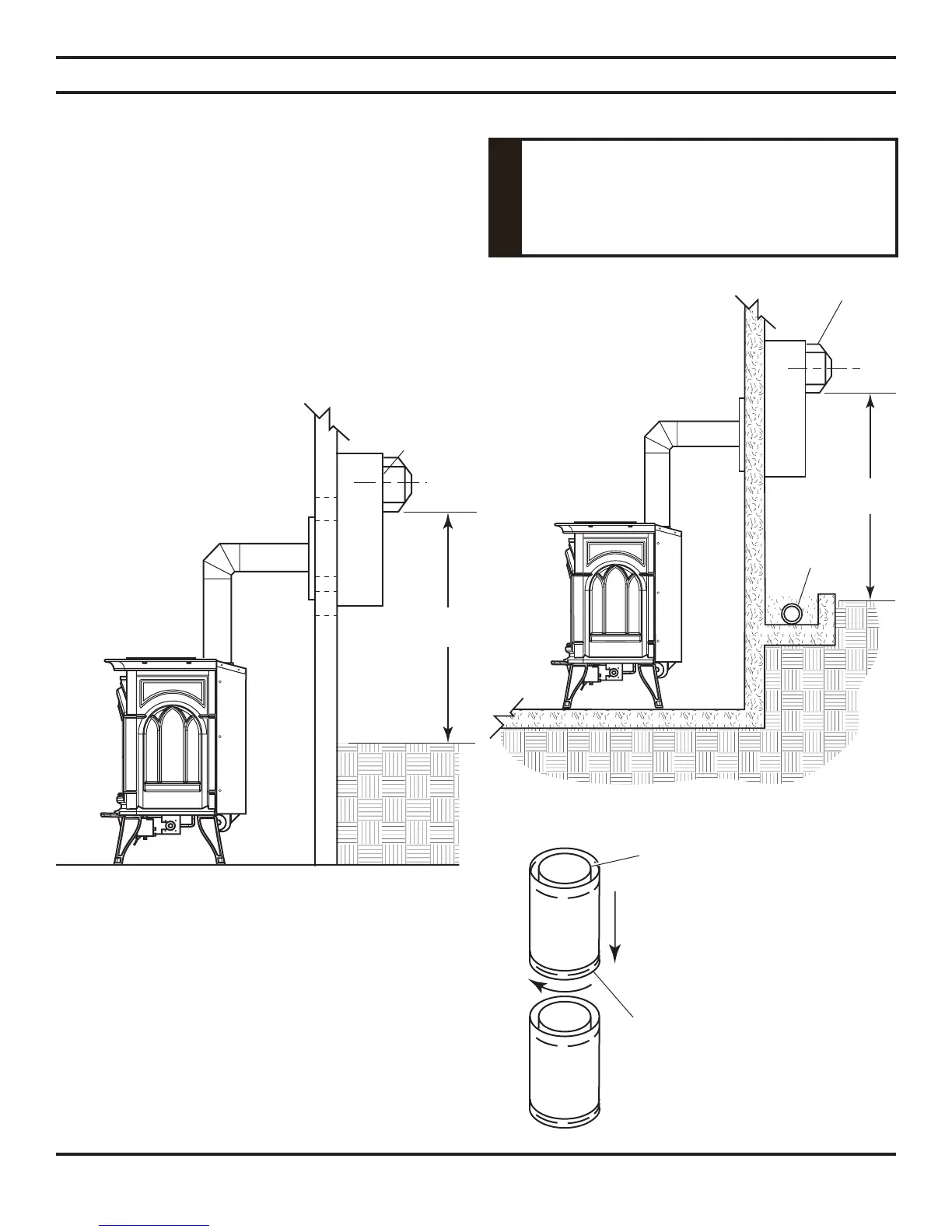
12"
Minimum
12"
Minimum
VENT INSTALLATION
INSTALLATION FOR HORIZONTAL TERMINATION
1. Determine the route your horizontal venting will take.
Note: The location of the horizontal vent termination
on the exterior wall must meet all local and national
building codes.
Do not recess vent terminal into a wall
or siding.
WARNING
Snorkel terminations are available for terminations requir-
ing a vertical rise on the exterior of the building. See Figures
12 and 13. Follow the same installation procedures used for
standard horizontal terminations. If installing the snorkel
termination below grade (basement applications), you must
provide proper drainage to prevent water from entering the
snorkel termination. See Figure 13. Do not back fill around
the snorkel termination.
2. Rigid vent pipes and fittings have special twist-lock con-
nections. Assemble the desired combination of pipe and
elbows to the appliance adaptor with pipe seams oriented
towards the wall or floor.
Twist-lock Procedure: The female ends of the pipes and
fittings have three locking lugs (indentations). These lugs
will slide straight into matching slots on the male end of
adjacent pipes and fittings. Push the pipe sections together
and twist one section clockwise approximately one-quarter
turn until the sections are fully locked. See Figure 14.
Figure 13 - Snorkel Termination with Drainage Pipe
Note: Horizontal runs of vent
must be supported every (3)
three feet (914mm). Use wall
straps for this purpose.
Figure 12 - Snorkel Termination
Snorkel
Snorkel
Adequate
Drainage
Figure 14 - Rigid Vent Pipe
Connections
Female
Locking Lugs
Male Slots
Continued