18 58D6056
HOT
H
V
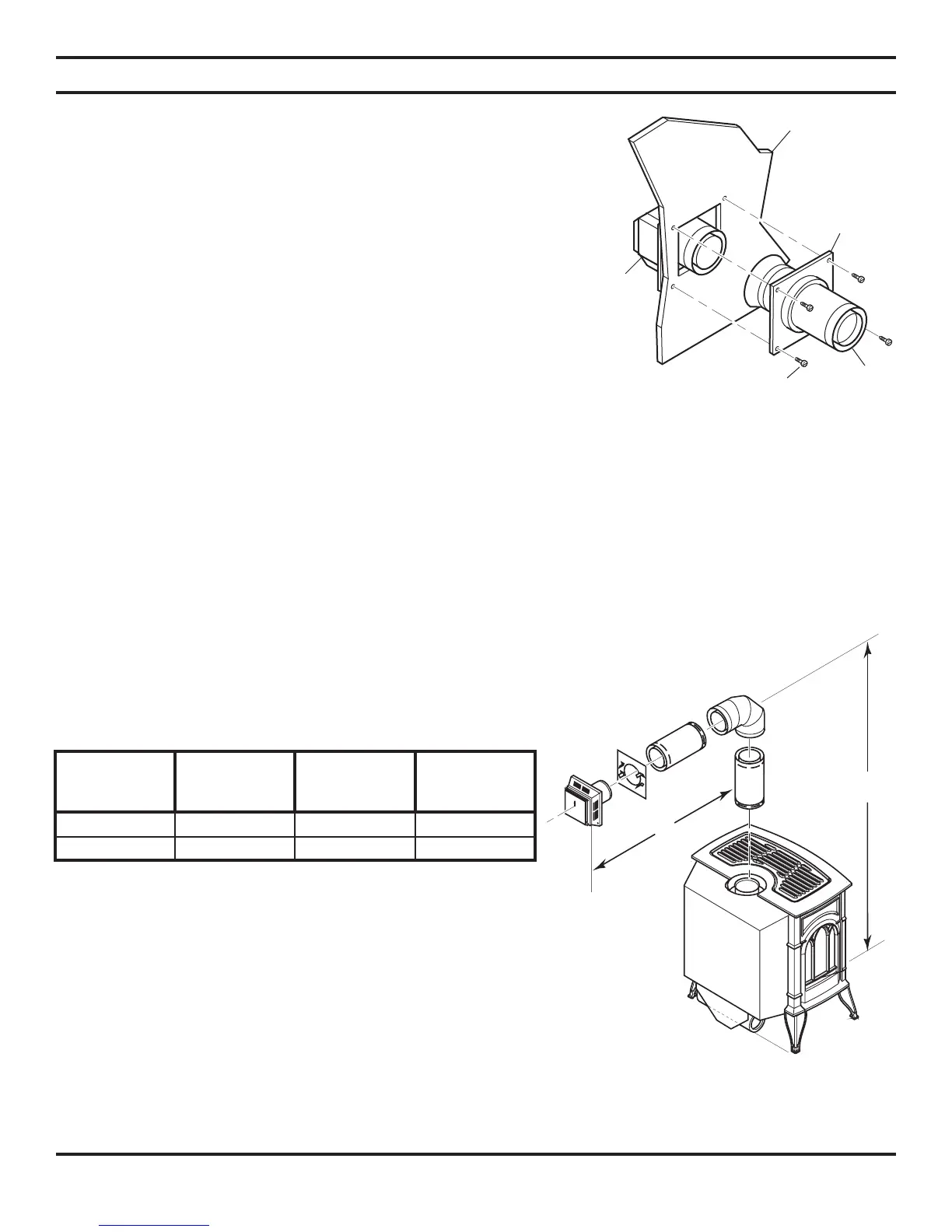
5. Slide the wall thimble over the vent pipe before connecting
the horizontal run to the vent cap. See Figure 18.
6. Carefully move the stove with vent assembly attached toward
the wall and insert the vent pipe into the horizontal termina-
tion. The pipe overlap should be a minimum of 1
1
/4" (mm).
Apply silicone to the outer pipe connection. Fasten all vent
connections with screws provided.
7. Slide the wall thimble against the interior wall surface and
attach with srews. See Figure 18.
Figure 18 - Connecting Vent Cap with
Horizontal Vent Pipe
VENT INSTALLATION
HORIZONTAL VENT INSTALLATION (continued)
Interior Wall
Surface
Decorative
Wall
Thimble
Horizontal
Vent Pipe
Screw
Vent Cap
(Horizontal
Termination)
HORIZONTAL TERMINATION CONFIGURATION EXAMPLES
Figures 19 through 21 show different configurations for venting and horizontal termination. Each figure includes a chart
with an example of horizontal maximum and vertical minimum dimensions taken from the chart on page 15.
Note: The horizontal run controls the minimum vertical height (i.e. the longer the horizontal run, the
higher the termination will be).
Follow the chart on page 15. All horizontal terminations require a
1
/4" rise per 12" of horizontal run.
NOTE: Add
1
/4" rise per 12" horizontal length of pipe.
Figure 19 - Horizontal Termination
Confi guration for Rigid Venting Using
One 90° Elbow
NOTE: This confi guration is for use with corner
installation also.
Maximum
Horizontal (H)
Vertical
Minimum
CSDV20 (V)
Vertical
Minimum
CSDV30 (V)
Vertical
Minimum
CSDV40 (V)
2' 41.50" 52.50" 54.50"
20' 95.25" 98.75" 102.25"
Table 2 - Horizontal Venting