Do you have a question about the LG DK676X and is the answer not in the manual?
Comprehensive safety guidelines for servicing video products, covering shock, fire, and X-radiation hazards.
Essential precautions for general servicing, including handling sensitive devices and insulation checks.
Technical specifications for power, outputs, system, and performance metrics of the device.
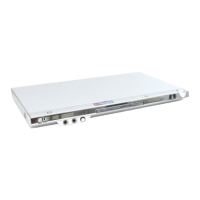
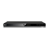
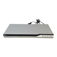
Visual representations of the product's internal components and their assembly.
Details and diagrams of the external cabinet and internal main frame structure.
Exploded view and component breakdown of the disc deck mechanism.
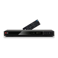
List and visual representation of included accessories and packing materials.
Step-by-step procedures and flowcharts for diagnosing and resolving electrical issues.
Flowchart for checking power supply voltages and identifying power-related faults.
Diagram illustrating the sequence of operations during system startup and playback.
Procedure for testing the unit and debugging system malfunctions.
Specific troubleshooting flowchart for the karaoke function.
Detailed analysis of system signals and waveforms for testing and debugging purposes.
Analysis of critical system clock, reset, and flash memory read/write signals.
Waveforms illustrating the signals controlling the disc tray mechanism.
High-level functional diagrams illustrating the system's architecture and component interactions.
A comprehensive block diagram showing the entire system architecture and interconnections.
Detailed schematic diagrams for various circuits, including power, system, servo, and timers.
Detailed schematic of the Switched-Mode Power Supply (SMPS) circuit.
Schematic diagram for the servo control circuits, including motor drivers.
Visual layouts of the main printed circuit boards with component placement.
Top view layout of the main printed circuit board.
Layout of the printed circuit board for timer functions.
| DVD Type | DVD player |
|---|---|
| Audio D/A Converter | 24-bit / 192 kHz |
| Progressive Scan | Yes |
| Video Output | Composite, Component, HDMI |
| Playable Disk Types | DVD, DVD-R/RW, DVD+R/RW, CD, CD-R/RW |
| Video D/A Converter | 108 MHz |
| Remote Control | Yes |
| Disc Compatibility | MP3, JPEG |
| Audio Output | Digital coaxial |
| Upscaling | 1080p |
| USB Port | Yes |