Air-to-Water Heat Pump _ 17
Part 1. Monobloc Unit
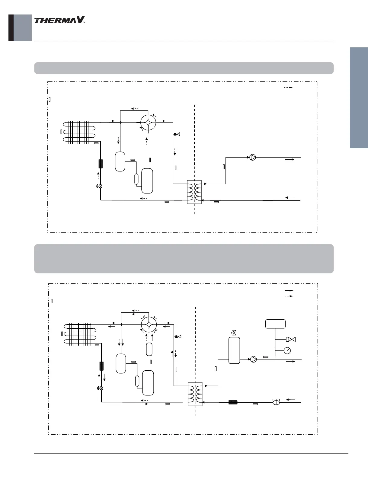
7. Piping Diagram
n
Refrigerant side / Water side
Th1
Th7 (Air)
: Heating
[Accumulator]
[Inv. Comp]
EEV
Th5
Th4
Th6
W/Pump_1
Th8
Th9
Th2
Th3
<Water Side><Refrigerant Side>
<Inside of Monobloc Product>
[PHE]
❈ EXP/Tank, E/Heater, Strainer, F/Switch are
not provided in product
Pressure
Sensor
4 way
Valve
Models : AHBW036H0 [HM031M]
: Cooling
: Heating
[Accumulator]
[Inv. Comp]
[Muffler]
[PHE]
EXP/TANK
Relief
valve
Pressure
Gage
Air Purge
Electric
Heater &
Tank
W/Pump_1
F/SStrainer
Th8
Th10
Th9
<Water Side><Refrigerant Side>
<Inside of Monobloc Product>
EEV
Th5
Th4
Th6
Th2
Th3
Pressure
Sensor
Th1
Th7 (Air)
Models : AHBW056A0 [HM051M] / AHBW076A0 [HM071M] / AHBW096A0 [HM091M]
AHBW126A0 [HM121M] / AHBW146A0 [HM141M] / AHBW166A0 [HM161M]
AHBW128A0 [HM123M] / AHBW148A0 [HM143M] / AHBW168A0 [HM163M]