33
General Installation Guidelines
Due to our policy of continuous product innovation, some specifications may change without notification.
©LG Electronics U.S.A., Inc., Englewood Cliffs, NJ. All rights reserved. “LG” is a registered trademark of LG Corp.
GENERAL INSTALLATION GUIDELINES
Piping Preparation
• Do not allow the refrigerant to leak during brazing; if the refrigerant combusts, it generates a toxic gas.
• Do not braze in an enclosed location, and always test for gas leaks before / after brazing.
• After brazing, check for refrigerant gas leaks.
3. Flaring the pipe end.
• Use the proper size flaring tool to finish flared connections as
shown.
• ALWAYS create a 45° flare when working with R410A. See Warn-
ing on this page.
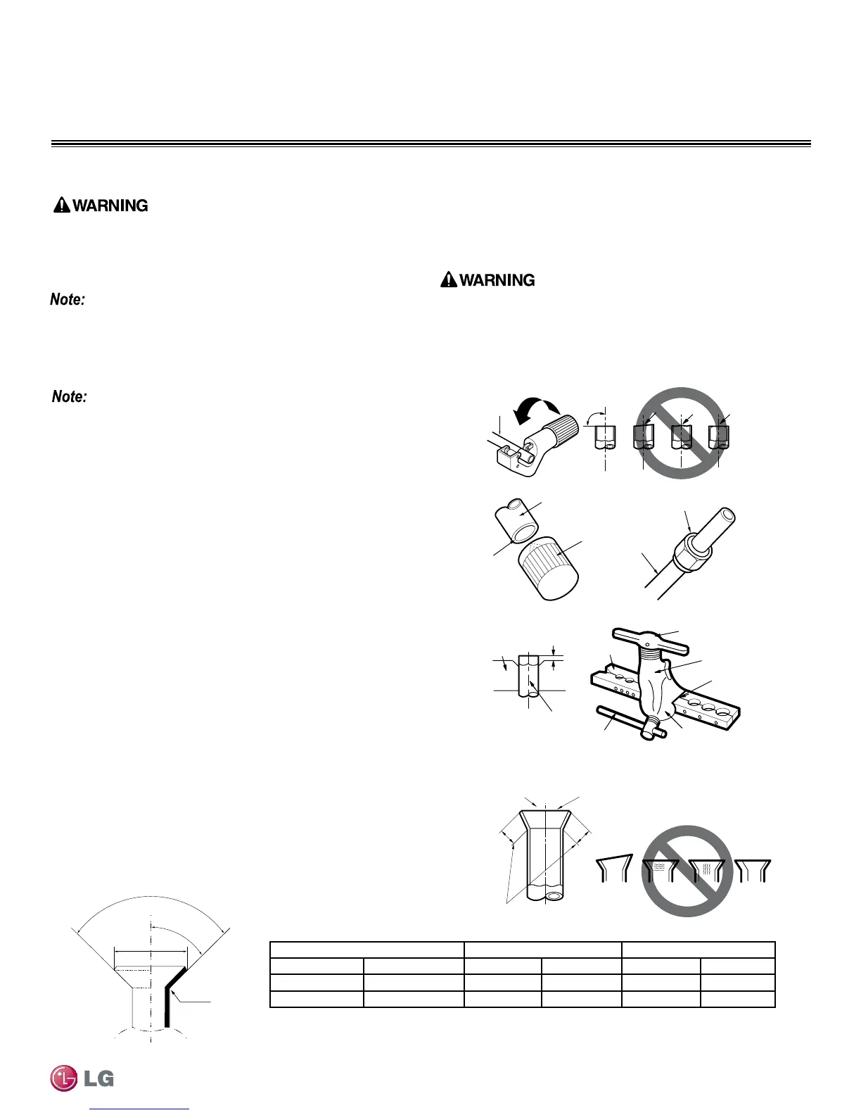
Creating a Flare Fitting
One of the main causes of refrigerant leaks is defective ared
connections. Create ared connections using the procedure below
(Figure 26).
1. Cut the pipe to length.
• Measure the distance between the indoor unit and the outdoor unit.
• Cut the pipes a little longer than measured distance.
• Cut the cable 4.9 ft longer than the pipe length.
2A. Remove the burrs.
• Completely remove all burrs from pipe ends.
• When removing burrs, point the end of the copper pipe down to
avoid introducing foreign materials in the pipe.
2B. Slide the flare nut onto the copper tube.
tube
90°
Slanted Uneven Rough
Pipe
Reamer
Point
down
Flare nut
Copper
tube
Bar
Copper pipe
Clamp handle
Red arrow
Cone
Yoke
Handle
Bar
"A"
Slanted
Inside is shiny with no scratches
Smooth
Even length
Damanged
surface
Cracked Uneven
thickness
Incorrect Flares
1.
2A. 2B.
3.
4.
4. Carefully inspect the flared pipe end.
• Compare the geometry with the figure to the right and dimensions
as detailed in Figure 25.
• If the flare is defective, cut it off and re-do procedure.
• If flare looks good, blow clean the pipe with dry nitrogen.
90°
2
45°
2
A
R=0.4~0.8
Figure 25: Dimensions of the Flare
Pipe “A” Thickness
Vapor (in. O.D.) Liquid (in. O.D.) Vapor (in.) Liquid (in.) Vapor (in.) Liquid (in.)
1/2 1/4 1/8 1/16 1/8 1/8
5/8 3/8 1/8 1/16 1/16 1/8
Table 11: Flared Connection Dimensions
Piping Preparation
1. Do not use kinked pipe caused by excessive bending in one
specific area on its length.
2. Braze the pipes to the service valve pipe stub of the outdoor unit.
When selecting are ttings, always use a 45° tting rated for use
with high pressure refrigerant R410A. Selected ttings must also
comply with local, state, or federal standards.
Figure 26: Creating a Flare Fitting
Single Zone Pipe Connections
 Loading...