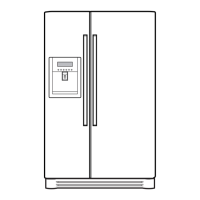
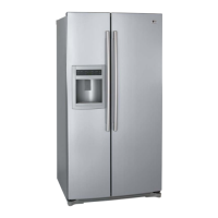
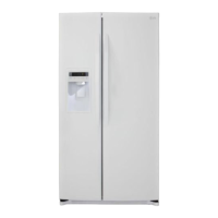
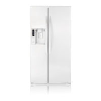
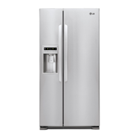
Do you have a question about the LG LSC26905TT and is the answer not in the manual?
Steps to level the refrigerator doors for proper alignment.
Instructions for replacing and flushing the water filter cartridge.
Detailed steps for installing and replacing the water filter.
Procedure to confirm and adjust water supply to the icemaker.
Using DIP switches to control water supply time for the icemaker.
Explains the different buttons and displays on the refrigerator's control panel.
Details the monitor panel for GR-L267BV(T)RA and GR-L267BV(T,S)PA models.
Details the monitor panel for the GR-L267BV(T)R model.
Details the monitor panel for the GR-L267BNRY model.
Explains buzzer mute, power saving, Celsius conversion, and demo modes.
Details various functional aspects of the refrigerator's operation.
How to select and adjust temperature settings for different compartments.
Describes how the ambient temperature is displayed on the unit.
How to lock/unlock the dispenser and control panel.
Selecting between water, crushed ice, and cubed ice.
How Express Freezing increases cooling speed.
Controls temperature for different food types in a specific compartment.
How MICOM controls the freezing fan speed.
Explains buzzer sounds for compulsory operations.
Describes the sequence of operations for built-in components.
Explains how the failure diagnosis function works and indicates error codes.
Explains the purpose and operation of various test modes.
Describes how the ice and water dispenser operates.
Details the power supply components and operation.
Explains the function of the oscillation circuit for clock signals.
Describes the circuit that restarts the MICOM from an initial state.
Details the load driving circuit and door opening detection.
Explains the dispenser operation circuit, load driving, and lever switch sensing.
Explains the circuit for detecting door opening and closing.
Describes the temperature sensing circuits for freezer and refrigerator.
Explains circuits for test switch and damper motor reed switch.
Explains circuits for model separation.
Details the stepping motor operation circuits for various models.
Explains fan motor driving circuits and voltage control.
Explains temperature compensation circuits and tables.
Describes compensation circuits for freezer temperature adjustment.
Explains communication between main and display PCBs via lead wires.
Table showing sensor resistance values at different temperatures.
Explains OptiChill stepping motor and display circuits.
Shows the diagram and lists parts for the main PWB assembly.
Lists components for the GR-L267BV(T)R model.
Shows the diagram and lists parts for the display assembly.
Shows the circuit diagram for the display.
Explains that PWB circuit diagrams can vary by model.
General principles of how the icemaker and dispenser operate.
Detailed working principles of the icemaker mechanism.
Detailed working principles of the ice and water dispenser.
Explains the specific functions of the icemaker.
Describes the initial setup and control of the icemaker.
Details how water is supplied to the icemaker.
Explains the process of ice formation within the icemaker.
Details the control function for ice ejection.
Explains the test function for icemaker operations.
Provides a troubleshooting flow chart for icemaker issues.
Shows circuit diagrams for the icemaker.
Circuit diagrams specific to the GR-L267BV(T)R model.
Circuit diagrams specific to the GR-L267BNRY model.
Circuit diagrams specific to the GR-L267BV(T)RA model.
Circuit diagrams specific to the GR-L267BV(T,S)PA model.
Identifies and resolves common electrical and component faults.
Addresses issues related to inadequate cooling performance.
Addresses issues with condensation and ice buildup inside the unit.
Diagnoses and resolves various operational sounds and vibrations.
Resolves electrical issues caused by internal voltage shorts or wiring.
| Brand | LG |
|---|---|
| Model | LSC26905TT |
| Category | Refrigerator |
| Language | English |