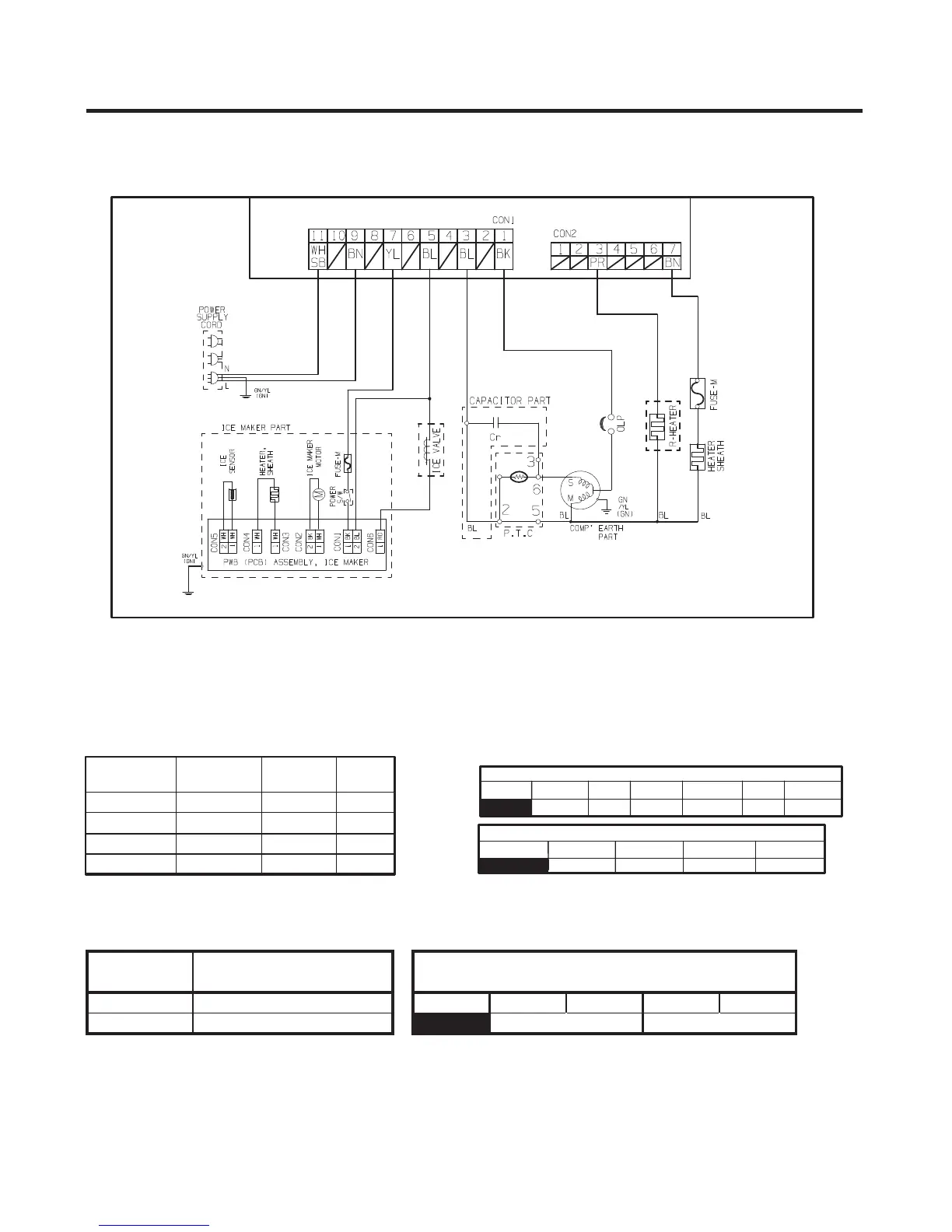
8-2-1 Power Circuit
Power is supplied to the control board at the pin 11 and 9 of connector #1. (Refer to figure 1)
FIGURE 1
8-2-2 Load and Door Light Circuit (HV)
1. Load Drive Condition Check
To measure outputs of the control board, check voltages between the pins for the following components:
(Refer to figure 1)
- 28 -
CONNECTOR 1
PIN 11 9 7 5 3 1
NEUTRAL LIVE L (I/M) N (I/M) N COMP
Circuit
Pin
Number
Pin
Number
Output
Voltage
Compressor Con 1 Pin 1 Con 1 Pin 3 115 VAC
Defrost Heater Con 2 Pin 7 Con 1 Pin 3 115 VAC
Ice Maker Con 1 Pin 7 Con 1 Pin 3 115 VAC
Pilot Valve Con 2 Pin 1 Con 1 Pin 3 115 VAC
CONNECTOR 2
PIN 7 5 3 1
DEF-HTR / R-HTR PILOT/V
2. Door Monitor Circuit (LV)
Refrigerator
Measurement between
pins 4 and 3 Con 8
Door Close 0 volts
PIN 1 2 3 4
Door Open 5 volts
RT-SNR R-DOOR S/W
CONNECTOR 8
 Loading...