- 29 -
PIN 1 2 3 4 5 6 7 8 PIN 1 2 3 4
N/C N/C N/C N/C
CONNECTOR 8
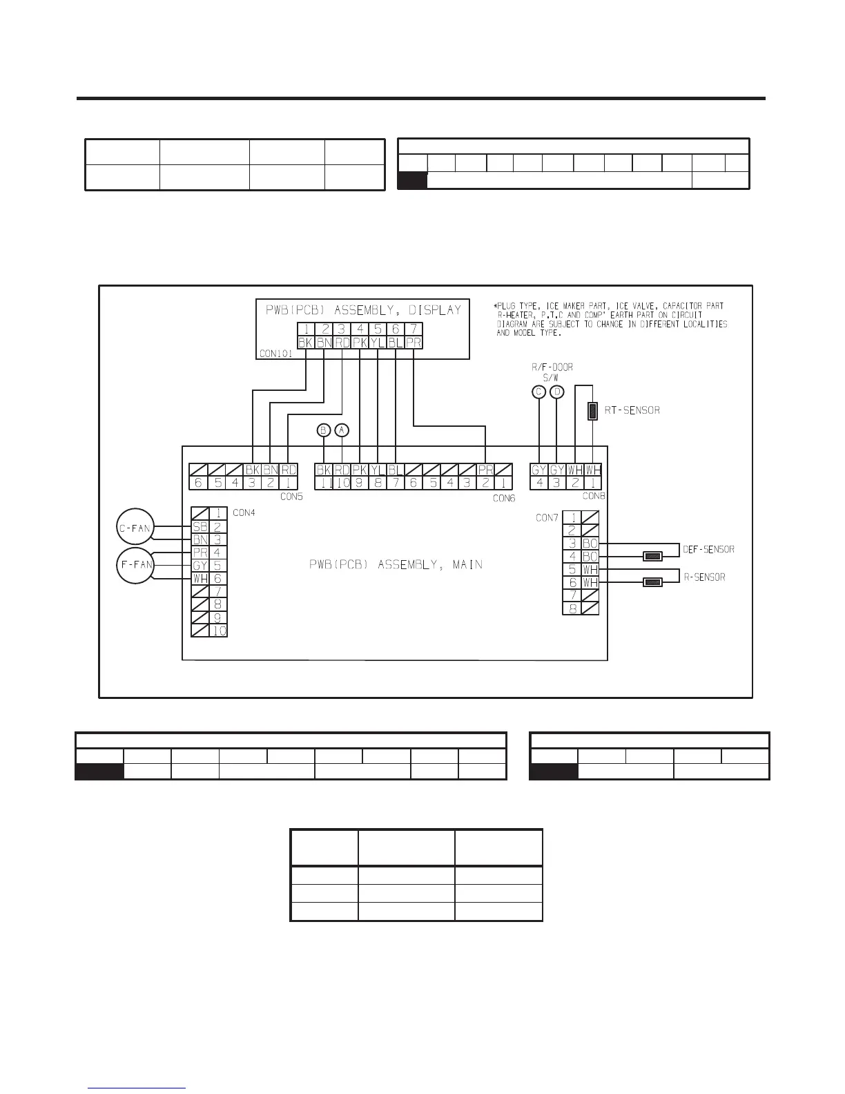
RT-SNR R-DOOR S/WD-SNR R-SNR
CONNECTOR 7
To measure the outputs of the sensors, check the voltages between the pins as in the table. And refer the values in the section
“RESISTANCE SPECIFICATION OF SENSOR”
SENSOR Pin Number Pin Number
D-SNR Con 7 Pin 3 Con 7 Pin 4
R-SNR Con 7 Pin 5 Con 7 Pin 6
RT-SNR Con 8 Pin 1 Con 8 Pin 2
3. LED Power Circuit (LV)
Circuit Pin Number Pin Number
Output
Voltage
LED Power Con 6 Pin 10 Con 6 Pin 11 12 VDC
CONNECTOR 6
PIN 1 2 3 4 5 6 7 8 9 10 11
DISPLAY 12V GND
volts indicates an open in the sensor circuit.
temperature in the compartments. A measurement of 0 volts indicates a short in the sensor circuit. A measurement of 5
Voltage supplied to each sensor wil range between 0.5 volts -22°F(-30°C) and 4.5 volts 122°F(50°C) depending upon the
8-2-3 Temperature Sensor Circuit (Refer to figure 2)
FIGURE 2
 Loading...