102 | LIMITS / PLACEMENT
MULTI V 5 Outdoor Unit Engineering Manual
'XHWRRXUSROLF\RIFRQWLQXRXVSURGXFWLQQRYDWLRQVRPHVSHFL¿FDWLRQVPD\FKDQJHZLWKRXWQRWL¿FDWLRQ
©
/*(OHFWURQLFV86$,QF(QJOHZRRG&OLIIV1-$OOULJKWVUHVHUYHG³/*´LVDUHJLVWHUHGWUDGHPDUNRI/*&RUS
PLACEMENT CONSIDERATIONS
Selecting the Best Location / Clearance Requirements for the Heat Recovery Unit(s)
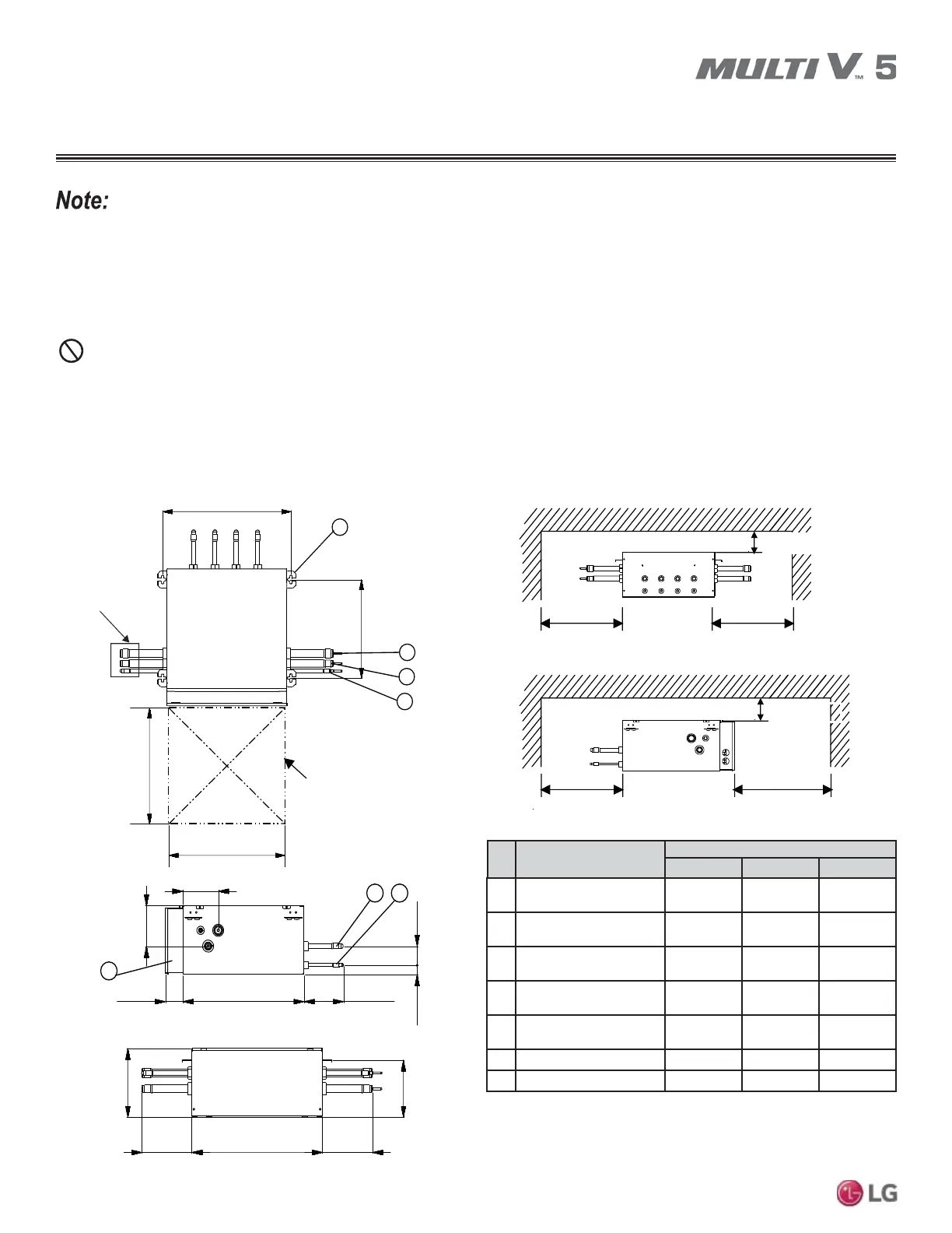
Select an installation space for the heat recovery unit that meets the following conditions:
• Install the heat recovery unit indoors in a level and upright position.
• Ensure there is enough space in the installation area for service access.
• Install the heat recovery unit in a location where any sound it may generate will not disturb occupants in the surrounding rooms.
• Install the refrigerant piping and electrical wiring system in an easily accessible location.
Dont’s
• Refrigerant pipes must not exceed lengths specified by LG Electronics.
• Do not install the heat recovery unit in a location where it would be subjected to strong radiation heat from heat sources.
• Avoid an installation environment where oil splattering or vapor spray may occur.
• Avoid an installation environment where high-frequency electric noise could occur.
• Condensate drain piping is not required.
1
Locate the inspection door at the control box side of the heat recovery
unit.
2
If reducers are used, space for service access must be increased to
match the dimensions of the reducer.
54
6
17-7/8
6-7/8
6-7/8
8-5/8
7-3/16
16-1/2
2-7/16
5-7/16
4-7/8
5-1/16
1-3/16
2-3/8
Inspection door
(servicing space)
18-15/16
13-5/8
1
2
3
7
17-3/4
17-3/4
1
Cap the pipes at the end of
series-connected branches
of heat recovery units.
11-13/16
more
11-13/16
more
11-13/16
more
17-3/4
more
Servicing space Servicing space
Servicing space
Servicing space
3-15/16 more
(Servicing space)
3-15/16 more
(Servicing space)
2
2
Tag
No.
Part Name
Connection Size(in.)/Type
PRHR022A PRHR032A PRHR042A
1
Low pressure vapor pipe
connection port
7/8 Braze 1-1/8 Braze 1-1/8 Braze
2
High pressure vapor pipe
connection port
3/4 Braze 7/8 Braze 7/8 Braze
3
Liquid pipe connection
port
3/8 Braze 1/2 Braze 5/8 Braze
4
Indoor unit vapor pipe
connection port
5/8 Braze 5/8 Braze 5/8 Braze
5
Indoor unit liquid pipe
connection port
3/8 Braze 3/8 Braze 3/8 Braze
6 Control box – – –
7 Hanger bracket 3/8 or 5/16 3/8 or 5/16 3/8 or 5/16
Figure 35: Dimensions for Heat Recovery Units.
Heat recovery units are for use with systems designed for heat recovery operation only.
Figure 36: Minimum Service Clearances for Heat Recovery Units.
Table 28: Heat Recovery Unit Parts.

 Loading...


