86 | ELECTRICAL CONNECTIONS
MULTI V 5 Outdoor Unit Engineering Manual
'XHWRRXUSROLF\RIFRQWLQXRXVSURGXFWLQQRYDWLRQVRPHVSHFL¿FDWLRQVPD\FKDQJHZLWKRXWQRWL¿FDWLRQ
©
/*(OHFWURQLFV86$,QF(QJOHZRRG&OLIIV1-$OOULJKWVUHVHUYHG³/*´LVDUHJLVWHUHGWUDGHPDUNRI/*&RUS
DIP SWITCH SETTINGS FOR USE WITH
GEN 4 INDOOR UNITS
Generation 4 Equipment
The latest versions of LG’s indoor units are designated Generation 4 (Gen 4). For Gen 4 indoor units to operate with Gen 4 indoor unit fea-
tures, the air conditioning system must meet the following requirements:
• All indoor units, heat recovery units, and air / water source units
must be Gen 4 or higher.
• All air / water source units must have Gen 4 or higher software
installed.
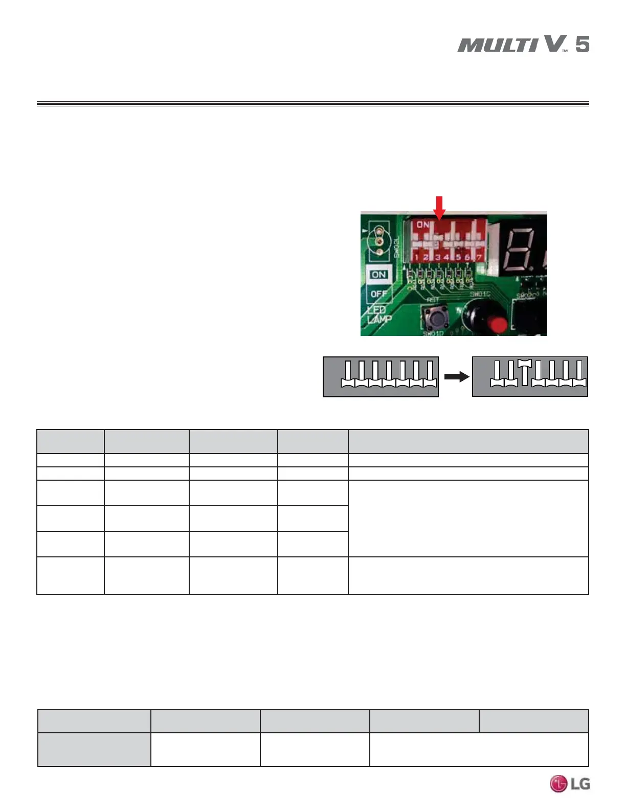
• Air / water source units DIP switch 3 must be set to ON
(factory default setting is OFF).
• All controllers must support Gen 4 indoor unit features.
The figure at right shows the outdoor unit DIP switch. The "System
Component Combinations and Operation Status" table lists how
combining different components will affect system operation. The
"Serial Numbers or Air / Water Source Units with Gen 4 or Higher
Software" table lists the serial numbers of air and water source
units that have Gen 4 or higher software. All air and water source
units, indoor units, heat recovery units, and controllers in a system
must be Gen 4 compatible or the system will not operate with Gen 4
indoor unit features.
Air / Water
Source Units*
Indoor Unit(s)** Heat Recovery Unit(s)
Outdoor Unit DIP
Switch No. 3
Operation Status
Gen 4 or Higher Gen 4 ONLY Model 2A ONLY Must be ON System will operate WITH Gen. 4 indoor unit features.
Gen 4 or Higher
Gen 4 ONLY Model 2A ONLY OFF System will operate but WITHOUT Gen. 4 indoor unit features.
Gen 4 or Higher Gen 4 ONLY
Any combination of
Models 1A, 2A
Must be OFF
(factory default)
Does NOT include Gen. 4 features. System will not operate if
DIP Switch No. 3 is ON, and an error code will be
generated.
Gen 4 or Higher
Any combination of
Gen 2 and Gen 4
Model 2A ONLY
Must be OFF
(factory default)
Gen 4 or Higher
Any combination of
Gen 2 and Gen 4
Any combination of
Models 1A, 2A
Must be OFF
(factory default)
Gen 2
Any combination of
Gen 2 and Gen 4
Any combination of
Models 0A****,
1A, 2A
N/A*** Does not include Gen. 4 features.
Figure 24: Location and Setting of Outdoor Unit DIP Switch 3.
12 76543
12 76543
ON
OFF
12 76543
12 76543
ON
OFF
Air/Water Source Unit DIP Switch No. 3
Table 18: System Component Combinations and Operation Status.
*Gen 4 or Higher Air / Water Source Units = Multi V 5, Multi V IV or Multi V Water IV with Gen 4 or Higher software (see table below for Gen
4 or higher serial numbers) or Multi V S.
Gen 2
Air / Water Source Units = Multi V II, Multi V III, Multi V IV without Gen. 4 software, Multi V Water II, Multi V Water IV without Gen. 4
software, Multi V Mini, Multi V Water Mini, or Multi V Space II.
**Gen 4 Indoor Units model numbers end in “4”; Gen 2 Indoor Units model numbers end in “2” or an “A”, including Hydro Kit.
***DIP Switch No. 3 on Gen 2 air / water source units is not related to Gen 4 features as it is with Gen 4 air / water source units.
****0A Model Heat Recovery units are not for use with Multi V 5, Multi V IV, Multi V Water IV, or Multi V III heat recovery systems.
Air / Water Source Unit
Model Type
Multi V Air Source
Heat Pump
Multi V Air Source
Heat Recovery
Multi V IV Water Source
Heat Pump
Multi V IV Water Source
Heat Recovery
Serial Number of Air / Water
Source Units with
Gen 4 or Higher Software
502********* and Higher 503********* and Higher 504********* and Higher
Table 19: Serial Numbers of Air / Water Source Units with Gen 4 or Higher Software.

 Loading...


