24 | ODU PRODUCT DATA
MULTI V 5 Outdoor Unit Engineering Manual
'XHWRRXUSROLF\RIFRQWLQXRXVSURGXFWLQQRYDWLRQVRPHVSHFL¿FDWLRQVPD\FKDQJHZLWKRXWQRWL¿FDWLRQ
©
/*(OHFWURQLFV86$,QF(QJOHZRRG&OLIIV1-$OOULJKWVUHVHUYHG³/*´LVDUHJLVWHUHGWUDGHPDUNRI/*&RUS
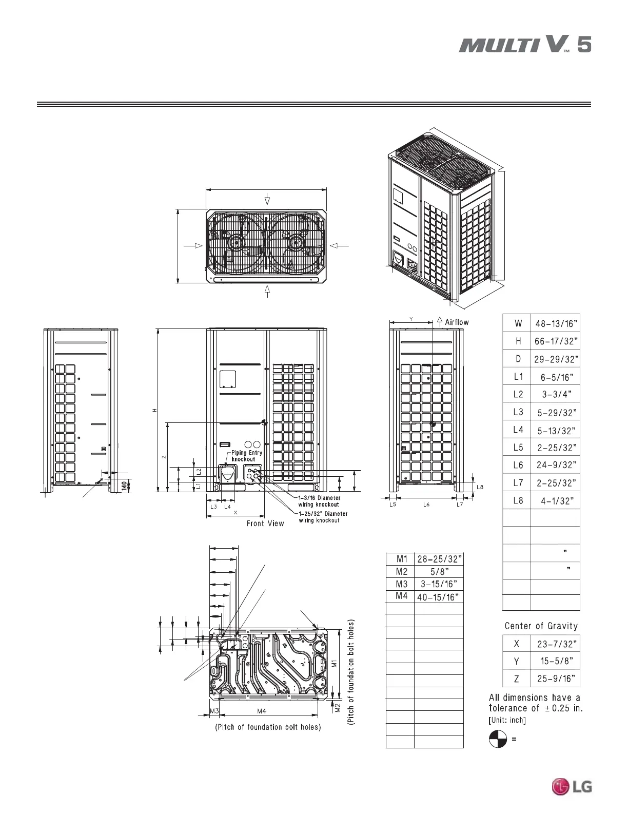
DIMENSIONS
ARUM096BTE5 / DTE5, 121BTE5 / DTE5, 144BTE5 / DTE5,
168BTE5 / DTE5, 192BTE5 / DTE5, 216BTE5 / DTE5, 241BTE5 / DTE5
M5
M8
M7
M6
M9
M10
M11
M12
M13
M14
M15
11 – 15/16”
11 – 1/16”
10 – 1/2”
8 – 7/16”
8 – 1/8”
6 – 1/16”
4 – 15/16”
7 – 1/2”
4 – 13/16”
4 – 5/16”
3”
L9
L10
7/8” Diameter Leak Test Hole
Left Side View
L9
L10
L11
L12
L13
L14
6 – 1/2”
5 – 9/16”
L11
L12
8 – 5/8
6 – 7/16
9 – 15/16”
L13
L14
3 – 5/8”
Right Side View
Two (2) 7/8” Diameter Wire
Routing Holes (Bottom)
M5
M6
M7
M8
M9
M10
M11
M12
M13
M15
M14
M16
Power Cord Routing Hole
(Bottom); two (2) - ø2”
Holes (Bottom);
two - ø2-5/8,”
ø2-1/8”
M16
3 – 5/8”
Piping
Routing
Center of Gravity
19/32” Dameter Hole
Bottom Mounting Holes
Airflow
Airflow
Top View
Airflow
D
W
Airflow
D
W
H
Note: Please refer to multi-frame
placement information and piping
rules in the Multi V 5 Engineering
Manual and the Multi V 5 Installation
Manual. Minimum spacing
between frames is 1 inch.

 Loading...


