109
Pre-commissioning and Maintenance
Due to our policy of continuous product innovation, some specifications may change without notification.
©LG Electronics U.S.A., Inc., Englewood Cliffs, NJ. All rights reserved. “LG” is a registered trademark of LG Corp.
Preparing the Water Circuit
1. Verify the specified waterside piping specialties such as temperature and pressure gauges, Pete’s plugs, water balancing valves, shutoff
valves, strainers, air vent(s), etc., were installed.
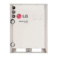
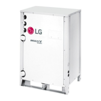
2. Verify the water circuit pump is operating correctly and the proper flow and temperature of water is provided to the water source unit.
3. Thoroughly flush the water circuit. Continually check and clean strainers as necessary. Continue flushing until strainers remain clean.
4. Purge all air from the water circuit. Check all auto or manual air valves installed.
Balance the Water Circuit Flow Distribution
The water flow balancing contractor must complete their work prior to commissioning and verifying the water flow rate is within project
specifications. Excessive or restricted water flow may impact the ability of the Commissioning Agent to successfully complete system com-
missioning. It is best if the water flow balancing is completed prior to initiating a request for a Commissioning Agent. Upon completion of the
waterside balancing, the report should provide the maximum flow rate (GPM) at the water source unit.
The Commissioning Agent is not responsible for setting the water ow rate, only to spot check. If a
problem exists, request verication from the Test and Balance technician. If necessary, provide
instruction to the technician on how to adjust the setting(s).
To prevent the heat exchanger from freezing, drain water out of the unit before charging the refrigerant.
Close
Close
Slave WSU
Close
Close
Master WSU
Indoor unit
Indoor unit
Indoor unit
Indoor unit
Liquid pipe
Vapor pipe
High-pressure
vapor pipe
Close
Close
Heat
recovery
unit
Liquid side
Low-pressure
vapor pipe
Low-pressure
vapor side
High-pressure
vapor side
Vacuum
pump
Liquid pipe
Vapor pipe
Liquid pipe
Vapor pipe
Liquid pipe
Vapor pipe
Liquid pipe
Liquid
Pipe
Low-press
vapor pipe
High-press
vapor pipe
Figure 86: Heat Recovery System Vacuum Conguration
PRE-COMMISSIONING
Prepare the Refrigerant Piping System

 Loading...


