Due to our policy of continuous product innovation, some specifications may change without notification.
©LG Electronics U.S.A., Inc., Englewood Cliffs, NJ. All rights reserved. “LG” is a registered trademark of LG Corp.
126
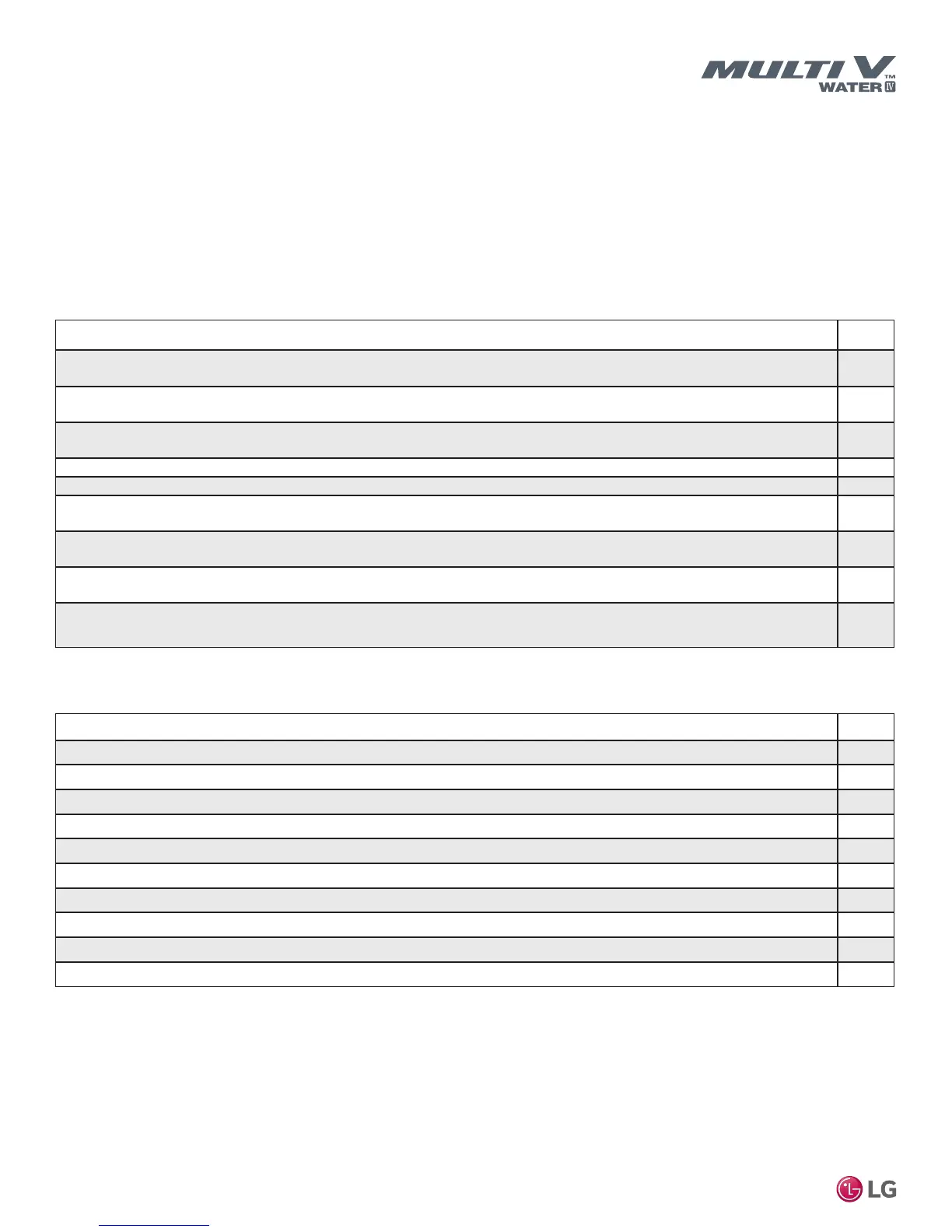
PRE-COMMISSIONING CHECKLIST
Page 1
Job Name / Location ________________________________________________________________________ Tag # _________________
Date: ____________________________________________________________________________________
Address: _________________________________________________________________________________
_________________________________________________________________________________
Refrigerant Circuit Preparation
Description Check
Using a copy of the LATS Multi V pipe design diagram, verify the sum of the indoor units nominal capacities connected to the pip-
ing system is between 50% and 130% of the water source unit’s nominal capacity. If this rule is violated, the system will not start.
Check all indoor units for power at the unit disconnect and at the indoor unit PCB board. (LED is lit.) DO NOT TURN ON THE
UNIT using the ON/OFF button.
Successful auto address routine is complete. All device addresses have been recorded on the Indoor Unit Device Configuration
Worksheet.
Insure all field-installed full-port ball valves are open.
The piping system held a constant 550 psig pressure for a minimum of 24 hours with all isolation valves open.
A triple system evacuation has been performed. Micron gauge reading held at a minimum of 500 for 24 hours with all isolation
valves open and without the vacuum pump connected.
Power was energized to the water source unit at ______________(time) on __________day to power the compressor crankcase
heater(s). (Must be at least 6 hours before commissioning.)
The communications cable to the indoor units has been disconnected from the IDU (B) and IDU (A) terminals at the water source
unit.
None of the water source unit service valves have been opened during the installation and preparation of the system for
commissioning. (If the valves were opened, the factory refrigerant charge has been released.)
Water Circuit Verification
Description Check
System has been pressure tested to the designer's requirements. All unions and fittings are leak free.
System has been filled with fluid, flushed, and all air has been purged from the piping circuit.
Pump rotation direction is correct.
Water flow enters on the water source unit inlet and leaves from the unit outlet.
Pump and water source unit strainers are clean.
Water balance has been completed.
Proper water flow rate is present at each water source unit.
Flow switch has been calibrated to trip at the water source unit's minimum flow requirement.
Water has been properly treated with a rust inhibitor and fungicide chemicals.
If required, an antifreeze chemical has been added to the water circuit.

 Loading...

